Bender COMTRAXX CP9 Kit Series Installation Manual
Graphical interface kit
Hide thumbs
Also See for COMTRAXX CP9 Kit Series:
- Quick start manual (9 pages) ,
- Quick start manual (8 pages)

Subscribe to Our Youtube Channel
Related Manuals for Bender COMTRAXX CP9 Kit Series


Summary of Contents for Bender COMTRAXX CP9 Kit Series
- Page 1 Manual COMTRAXX® CP9xx–Kit Installation kit graphical interface Softwareversion: V3.xx CP9xx-Kit_D00399_00_M_XXEN/07.2019...
- Page 2 Bender GmbH & Co. KG © Bender GmbH & Co. KG P.O.Box 1161 • 35301 Gruenberg • Germany All rights reserved. Reprinting only with permission Londorfer Straße 65 • 35305 Gruenberg • Germany Tel.: +49 6401 807-0 • Fax: +49 6401 807-259 of the publisher.
-
Page 3: Table Of Contents
Table of Content 1. Important information ................... 5 How to use this manual ......................5 Technical support: service and support ................6 1.2.1 End customer support and consulting ..............6 1.2.2 Repair ........................... 6 1.2.3 Customer service ......................6 Training courses ........................6 Delivery conditions ......................... - Page 4 Table of Content Connection of the CP9xx-Kit ....................16 Connections ..........................17 4.4.1 Factory settings communication addresses ............17 Digital inputs and outputs ....................19 4.5.1 Functions .......................... 19 4.5.2 Mode ..........................19 4.5.3 Response times t(on)/t(off) ..................19 Commissioning of the CP9… device ................20 COMTRAXX®...
-
Page 5: Important Information
The "BMS bus" package slip COMTRAXX® is a registered trademark of Bender GmbH & Co. KG. Always keep this manual within easy reach for future reference. We have used symbols to identify important instructions and information: This signal word indicates that there is a high risk of danger, that will result in death or serious injury if not avoided. -
Page 6: Technical Support: Service And Support
**Mo-Thu 7.00 a.m. - 4.00 p.m., Fr 7.00 a.m. - 1.00 p.m 1.3 Training courses Bender is happy to provide training regarding the use of test equipment. The dates of training courses and workshops can be found on the Internet at www.bender.de -> Know-how -> Seminars. -
Page 7: Delivery Conditions
Important information 1.4 Delivery conditions The conditions of sale and delivery set out by Bender apply. These can be obtained from Bender in printed or electronic format. For software products, the "Softwareklausel zur Überlassung von Standard- Software als Teil von Lieferungen, Ergänzung und Änderung der Allgemeinen Lieferbedingungen für Erzeugnisse und Leistungen der Elektroin-... - Page 8 Important information CP9xx-Kit_D00399_00_M_XXEN/07.2019...
-
Page 9: Safety Instructions
These include, for example: All Bender devices with BMS bus or BCOM interface Bender devices (PEM, energy meters,…) with Modbus RTU or Modbus TCP interface Other devices with Modbus RTU or Modbus TCP interface ... - Page 10 Safety instructions CP9xx-Kit_D00399_00_M_XXEN/07.2019...
-
Page 11: Product Description
3.4 Applications Optimal visualisation on the display tailored to the user Integration of all compatible Bender products (ISOMETER®, ATICS®, RCMS, EDS, Linetraxx® and MEDICS® systems, universal measuring devices and energy meters) Individual instructions in case of alarms ... -
Page 12: Function
CP9… alarm indicator and operator panels are integrated into the existing EDP structure like PCs. After con- nection to the network and compatible Bender products, all system devices can be accessed from any PC using a web browser. In this way, all important system information is directly available. Verified web browsers: Mi- crosoft IE, Mozilla Firefox, Google Chrome The possibility of integrating all technical equipment into a single panel creates a "technical monitoring centre"... -
Page 13: Address Configuration And Termination
Multiple assignment of addresses The factory setting for the system name on all Bender BCOM devices is "SYS- TEM". If several systems with the same system name are integrated into the sa- me network, addresses are assigned twice. This leads to transmission errors. - Page 14 Product description CP9xx-Kit_D00399_00_M_XXEN/07.2019...
-
Page 15: Installation, Connection And Commissioning Cp9Xx-Kit
4. Installation, connection and commissioning CP9xx-Kit The CP9… touch panel is integrated into existing LAN structures, but can also be operated via a single PC. Only qualified personnel are permitted to carry out the work necessary to ins- tall, commission and run a device or system. Configuration of computer networks If you are familiar with the configuration of computer networks, you can carry out the connection of the CP9…... -
Page 16: Drillholes
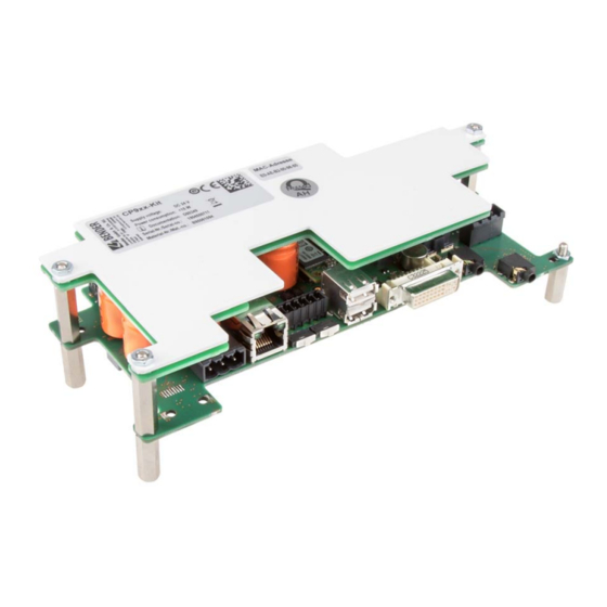
Installation, connection and commissioning CP9xx-Kit 4.2.1 Drillholes Abb. 4.3: Drillholes of the CP9xx-Kit * Damage due to excessive torque. Tighten all screw connections with a torque of 0.6 Nm. Otherwise the circuit boards will be damaged. CAUTION 4.3 Connection of the CP9xx-Kit Digital I/O Relais Relay... -
Page 17: Connections
Installation, connection and commissioning CP9xx-Kit 4.4 Connections If you are familiar with the configuration of computer networks, you can carry out the connection of the CP9… alarm indicator and operator panel yourself. Otherwise please contact your EDP administrator! For UL-applications: Minimum temperature rating of the cable to be connected to the field wiring ter- minals: 75 °C Connection... - Page 18 Installation, connection and commissioning CP9xx-Kit Connect the CP9xx-Kit as follows: 1. Modbus RTU connection: Connect terminals AMB and BMB (7) to the Modbus RTU (A to A, B to B). 2. BMS bus connection: Connect terminals ABMS and BBMS (7) to the BMS bus (A to A, B to B). AMB BMB SMB ABMS BBMS SBMS...
-
Page 19: Digital Inputs And Outputs
Installation, connection and commissioning CP9xx-Kit 9. Connect the screen output DVI (10) to the front plate. Appropriate DVI-D connecting cable included in scope of delivery. DVI-D-Anschluss Steuerplatine 4.5 Digital inputs and outputs CP9xx devices have 12 configurable digital inputs and outputs. The settings are made via the COMTRAXX® user interface in a browser. -
Page 20: Commissioning Of The Cp9
Installation, connection and commissioning CP9xx-Kit 4.6 Commissioning of the CP9… device 1. Switch on the supply voltage: After switching on, the device performs a start routine. It is completed when the commissioning page appears n the display. Abb. 4.5: Commissioning page CP9xx device 2. -
Page 21: Comtraxx® User Interface Of The Cp9Xx-Kit
Installation, connection and commissioning CP9xx-Kit 4.7 COMTRAXX® user interface of the CP9xx-Kit The device has a web user interface for setting and operation. How to start the web interface: – Open an Internet browser from any network device. – Enter the address of the CP9… device into the address line of the browser. It is possible to connect the CP9…... - Page 22 Installation, connection and commissioning CP9xx-Kit CP9xx-Kit_D00399_00_M_XXEN/07.2019...
-
Page 23: Modbus Tcp Server
5. Modbus TCP server 5.1 Data access using Modbus TCP protocol Requests are sent to the Modbus TCP server of the CP9… using function code FC4 (read input register). The server generates a function-related response and sends it to the Modbus client. 5.1.1 Exception code If a request cannot be answered for whatever reason, the server sends a so-called exception code with which possible faults can be narrowed down. -
Page 24: Structure Of The Exception Code
Modbus TCP server 5.1.4 Structure of the exception code Byte Name Example … … … Byte 7 MODBUS function code 0x84 Byte 8 Exception code 0x01 or 0x02 5.1.5 Modbus address structure for BMS devices Number of Function Address range Number of bytes words Device type... -
Page 25: Memory Scheme Of The Process Image
Modbus TCP server 5.2.2 Memory scheme of the process image 5.2.2.1 Structure of the process image As illustrated in the table, the Modbus start address for the respective process image is derived from the device address. 256 (0x100) words or 512 bytes are reserved for each device. They contain all the information reques- ted and transmitted from the bus. - Page 26 Modbus TCP server Channel 21 Channel 22 Channel 23 Channel 24 Channel 25 Channel 26 Channel 27 Channel 28 Channel 29 Channel 30 Channel 31 Channel 32 R R R R R R R R R R R R R R R R R R R R R R R R R R R R R R R R R R R R R R R R R R R R R R R R R R R R R R R R R R R R R R R R 0xC0 R R R R R R R R R R R R R R R R R R R R R R R R R R R R R R R R...
- Page 27 Modbus TCP server 5.2.2.6 Channels 1 to 32 with analogue and/or digital values Word 0x00 0x01 0x02 0x03 HiByte LoByte HiByte LoByte HiByte LoByte HiByte LoByte Floating point value (Float) AT&T R&U Channel description Every analogue device channel can contain alarm messages, operating messages, measured values, test mes- sages and descriptive text.
- Page 28 Modbus TCP server 5.2.2.9 R&U = Range and unit Meaning Invalid (init) No unit Ω Baud °C °F Second Minute Hour Month … … … … … Reserved CODE Reserved … … … … … Reserved Reserved Actual value The actual value is lower The actual value is higher Invalid value The units of the bits 0 to 4 are coded.
- Page 29 Modbus TCP server 5.2.2.10 Channel description Word 0x03 Byte HiByte LoByte deci Meaning Reserved Insulation fault Overload Overtemperature Failure line 1 Failure line 2 Insulation OT light Reserved Failure distribution board Oxygen Vacuum Anaesthetic gas Compressed air 5 bar … … … … … … … … … … … … … … … … … …...
-
Page 30: Modbus Examples To Read Out Data
Modbus TCP server 5.2.3 Modbus examples to read out data Example: Reading out from ATICS channel 1 (voltage line 1) CP9… has address 1 in subsystem 1. ATICS channel 1 of internal address 3 is to be read out. The content is the voltage of line 1 as floating point value. -
Page 31: Channel Descriptions For The Process Image
Modbus TCP server 5.2.4.2 Reference value on channel 1 The following reference value is stored in this channel: 230.0 V undervoltage Word 0x10 0x11 0x12 0x13 HiByte LoByte HiByte LoByte HiByte LoByte HiByte LoByte 0x43 0x66 0x00 0x00 0x00 0x04 0x00 0x4D Floating point value (Float) - Page 32 Modbus TCP server Measured value description Value Note alarm message operating Failure line 2 5 (0x05) Insul. OT light Insulation fault operating theatre light 6 (0x06) 7 (0x07) Failure distribution board 8 (0x08) Failure oxygen 9 (0x09) Failure vacuum 10 (0x0A) Anaesthetic gas 11 (0x0B) Compressed air 5 bar...
- Page 33 Modbus TCP server Measured value description Value Note alarm message operating Undervoltage 77 (0x4D) Overvoltage 78 (0x4E) Frequency Measured value in Hz 79 (0x4F) 80 (0x50) Asymmetry 81 (0x51) Capacitance Measured value in F 82 (0x52) Temperature Measured value in °C 83 (0x53) Overload Measured value in %...
- Page 34 Modbus TCP server Measured value description Value Note alarm message operating 134 (0x86) 135 (0x87) 136 (0x88) Short circuit Q1 137 (0x89) Short circuit Q2 138 (0x8A) CV460 CV460 fault 139 (0x8B) RK4xx Fault RK4xx 140 (0x8C) Address collision BMS address has been assigned several times 141 (0x8D) Invalid address 142 (0x8E)
-
Page 35: Modbus Control Commands
Modbus TCP server Value Description of parameters: Register address (unit not displayed) 1011 (0x3F3) Time 1010 (0x3F2) Factor multiplication [*] 1009 (0x3F1) Factor division [/] 1008 (0x3F0) Baud rate 1007 (0x3EF) 5.2.6 Modbus control commands Commands can be sent to BMS devices by an external application (e.g. visualisation software). This functionality can be activated or deactivated via the web user interface. - Page 36 Modbus TCP server Control commands for the internal and external BMS bus int/ext Register Register Register Register Menu text/ BMS bus Channel Command Function 1-150 Test Isometer 1-99 Test changeover unit (PRC487)/ 1-150 Test PRC changeover unit 1-99 Test changeover unit (ATICS)/ 1-150 Start automatic test changeover 1- >2...
- Page 37 Modbus TCP server 5.2.6.1 Modbus example for control commands Example: Changeover of ATICS to line 1 CP9… has address 1 in subsystem 1. An ATICS of internal address 3 is to be changed over to line 1. Modbus control command:00 02 00 00 00 0F 01 10 FC 00 00 04 08 00 01 00 03 00 00 00 05 00 02 Transaction ID (is generated automatically) 00 00...
-
Page 38: Troubleshooting
COMTRAXX® manual). Frequently asked questions on the Internet You will find FAQs on many Bender devices at: http://www.bender.de > Service & support > Rapid assistance > FAQ 6.2 Maintenance The device does not contain any parts that must be maintained. -
Page 39: Technical Data
7. Technical data Insulation coordination CP9xx-Kit acc. to IEC 60664-1 Rated voltage.................................50 V Overvoltage category ................................ III Pollution degree ................................2 Rated impulse voltage..............................800 V Supply CP9xx-Kit via plug-in terminal (A1/+;A2/-) Nominal voltage CP907........................DC 24 V SELV/PELV Nominal voltage tolerance............................+/-20 % Typical power consumption at DC 24 V........................ - Page 40 Technical data Modbus TCP Interface/protocol ..........................Ethernet/Modbus TCP Operating mode ..................Client for PEM and "third-party devices" assigned Operating mode ..........Server for access to process image and for Modbus control commands SNMP Versions ..................................1, 2c, 3 Devices supported ............Queries to all devices (channels) possible (no trap functionality) BMS bus Interface/protocol..........................
- Page 41 Device connections Terminal block (L1; N; PE) Conductor sizes..............................AWG 20-12 Stripping length.............................. 10…11 mm rigid/flexible ..............................0.5…4 mm² flexible with ferrule with/without plastic sleeve ..................0.5…4 mm² Multiple conductor, flexible with TWIN ferrule with plastic sleeve.............. 0.5…4 mm² Plug-in terminal (A1/+; A2/-; PE) (11; 12; 14) Conductor sizes ..............................AWG 24-12 Stripping length................................
-
Page 42: Ordering Details
Technical data 7.1 Ordering details 7.1.1 Devices Type Supply (W x H x D) Weight Front Art. No. CP9xx-Kit DC 24 V, < 15 W; SELV/PELV 200x 54 x 90 mm 0,36 kg B95061094 7.1.2 Accessories Type Description Art.-No. CP9… Vacuum lifter B95061911 CP9…... -
Page 43: Index
Index Modbus - Address structure for BMS devices Address 17 - control commands 35 - Function code 24 - Process image 24 BMS device address assignment on the - requests 23 Modbus 25 - responses 23 Byte offset 31 Byte or word swapping 31 Process image 25 Claims under the warranty 38 Connection... - Page 44 Bender GmbH & Co. KG Postfach 1161 • 35301 Grünberg • Germany Londorfer Straße 65 • 35305 Grünberg • Germany Tel.: +49 6401 807-0 • Fax: +49 6401 807-259 E-Mail: info@bender.de • www.bender.de Group Fotos: Bender Archiv.
Need help?
Do you have a question about the COMTRAXX CP9 Kit Series and is the answer not in the manual?
Questions and answers