
Related Manuals for Seresco CLASSIC NE Series


Summary of Contents for Seresco CLASSIC NE Series
- Page 1 NE Series Dehumidifiers NE-002 and NE-003 NE-204 and NE-206 CLASSIC Indoor Model Operation and Maintenance Manual Seresco Technologies Inc. Serescodehumidifiers.com...
-
Page 2: Table Of Contents
B –Table of Content Table of Content Chapter C - General Information C – 1 C – 1 Operating Safety C – 2 Reference and Additional Information Contact Us C – 2 C – 3 Basic Information Dehumidifier View and Options C –... - Page 3 B –Table of Content This page is left blank...
-
Page 4: Chapter C - General Information
C – General Information General Information This manual provides basic information about the applicable Seresco dehumidifier and its operation. Important information regarding installation, maintenance, and start up as well as additional and auxiliary systems and devices (outdoor condenser, communication interfaces, etc.) is normally provided with the dehumidifier and can also be obtained at Seresco (see Contact Us below). -
Page 5: Reference And Additional Information C
Failure to do so could negatively affect premise comfort levels and people’s health. It could also lead to equipment damage, malfunction, premature tear and ware and may void equipment warranty. Contact Us Seresco Technologies website: http://serescodehumidifiers.com Seresco Online Service Center website: http://service.serescodehumidifiers.com Headquarters Customer Support Team 1071 Ages Drive Email: customersupport@serescodehumidifiers.com... -
Page 6: Basic Information
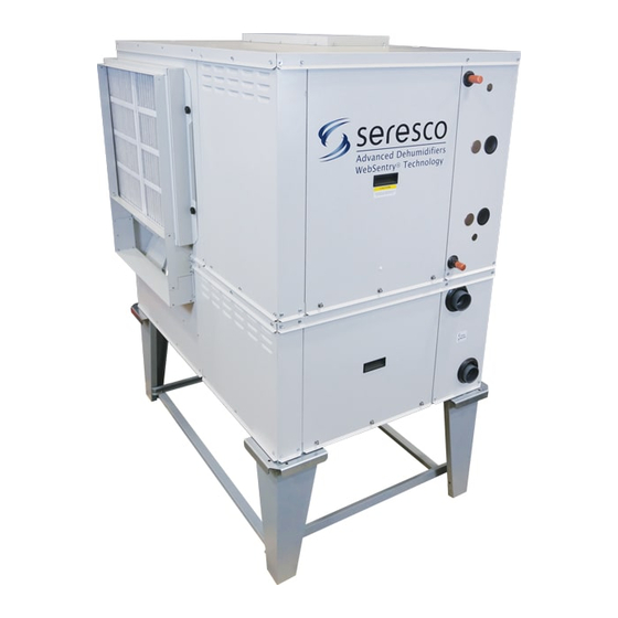
C – General Information Basic Information Dehumidifier View and Options Standard NE002 – NE003 dehumidifier’s general view and options * are shown on Pic.C.1. Options: Return Air (RA) ductwork connection - horizontal. Supply Air (SA) ductwork connection options – top, bottom, horizontal*. ... -
Page 7: Dehumidifier External Systems Connection C
C – General Information All available options (tonnage, ductwork connections, AC options etc.) are shown. Refer to the submittal and other relevant documentation for your equipment options, dimensions etc. The pool water heating option relies on compressor-created excess heat and is used as an additional heating source. -
Page 8: Dehumidifier Optional Arrangement C
C – General Information Dehumidifier Optional Arrangement. Two-Compressor Arrangement Standard NE series dehumidifier has one compressor, however two-compressor arrangement is available also. Note, that all options and details, provided above, apply to both, standard and two-compressor arrangement: “Double-Decker” dehumidifier is shown on Pic. C.3. It is composed of two identical dehumidifiers, one installed on top of another and controlled as a single dehumidifier (each deck is equipped with one compressor/refrigeration... -
Page 9: Air Conditioning Options - Outdoor Air Condensers And Fluid Coolers C
C – General Information Air Conditioning Options - Outdoor Air Condensers (OACC) and Fluid Coolers (OAFC). Basic views of standard air conditioning options are shown on Pic.C.4 (below); standard combinations of the dehumidifier and respective air conditioning option (based on their capacities) are shown in Table C.1. Table C.1 shows standard dehumidifier and Table C.1. -
Page 10: Equipment Specific Data C
C – General Information Equipment Specific Data Specific information for individual dehumidifiers is provided in the following methods: Main Label (Pic. C.5): the manufacturer tag attached to the front of the dehumidifier includes the dehumidifier’s most critical data: General data including: Serial number Dehumidifier model (nomenclature) Design room conditions (air temperature... - Page 11 C – General Information This page is left blank...
-
Page 12: Chapter D - Layout And Components
D – Layout and Components Layout and Components The general layout and components location is the same for all dehumidifiers of current type, however some may vary, based on the dehumidifier’s specific options – refer to submittal documentation. Pic. D.1 below shows all/most available options, some of which may not be present on your dehumidifier. -
Page 13: Control System D
D – Layout and Components Main Blower (1) is in the main blower compartment next to the Main Electric Panel (2) and Compressor Compartment (3). Min Outdoor Air (OA) Opening (4) is optionally equipped with a motorized damper and filter(s). The Manual OA Damper (5) is usually used to set proper amount of outdoor air intake. - Page 14 D – Layout and Components Pic. D.4 RA Combo Sensor (21) measures temperature and humidity of the pool room air (Return Air) entering the dehumidifier. It is located at the main filter rack. OA Temperature Sensor (22) measures outdoor air temperature; it’s located at the OA filter rack. As an option, the combo sensor (instead of regular thermistor) can be installed at the OA intake to measure both the temperature and humidity of the outdoor air.
-
Page 15: Outdoor Air Condensers And Fluid Coolers Layout And Components
D – Layout and Components Outdoor Air Condensers and Fluid Coolers Layout and Components The general layout of AC options (air-and water-cooled) is shown on Pic.D.5 below with the outdoor air condenser NC-B-1 (left) and fluid cooler NG-V-0 (right) as an example. While layout and main components are similar for all applicable AC options, there are some deviations (number of fans, coil sizes, composition, etc.). - Page 16 D – Layout and Components Fluid Coolers Pump Package Fluid Coolers, if equipped with such option, would have a pump package box. Pic.D.6 below shows general layout of pump packages, used for NG-Z (left) and NG-V (right) fluid coolers. Note that the package used with NG-V coolers could be mounted onto the fluid cooler directly (standard) or provided separately.
- Page 17 D – Layout and Components This page is left blank...
-
Page 18: Chapter E - Sequence Of Operation
E – Sequence of Operation Sequence of Operation The dehumidifier’s ventilation system establishes the required airflow through the dehumidifier. The control system compares air temperature and humidity to their desired values (set points) and proceeds to dehumidify, cool or heat the recirculating air. If the dehumidifier is equipped with the pool water heating option, the pool water temperature is compared to its set point and pool heating is provided if required. - Page 19 E – Sequence of Operation Compressor Circuit Operation Piping schematic for compressor circuit is shown on Pic. E.1. When a demand requires the compressor to operate, the following sequence occurs: Once blower operation, related safeties and timers are confirmed by the control system, the pump down solenoid valve opens and once pressure stabilizes, the compressor starts.
-
Page 20: Space Heating
E – Sequence of Operation Space Heating When premise air temperature drops below the set point, the dehumidifier control system issues a call for Space Heating Mode and engages space heater (electric heater, hot water coil with valve, gas boiler etc.) by sending space heating signal, respective to space heater control type - on/off, variable (0-10VDC), etc. - Page 21 E – Sequence of Operation This page is left blank...
-
Page 22: Chapter F - Interface And Communication
F – Interface and Communication Interface and Communication Touch Display Operator Panel The Touch Display Operator Panel (OP), shown on Pic. F.1, is used as a main interface between the dehumidifier and operator. The same OP can be located in the dehumidifier main electric panel (default; used as a local OP) or installed remotely from the dehumidifier ... -
Page 23: Alarms F
F – Interface and Communication Alarms If the dehumidifier control system detects abnormal or unsafe for further operation situation, it issues Alarm (notification of such situation accompanied by respective component or entire dehumidifier stoppage and/or lockout) or Alert (notification of minor abnormal situation without any devices’ stoppage or lockout). All alarms and alerts are recorded and can be viewed/cleared via the Touch Display OP: ... -
Page 24: Remote Communication F
F – Interface and Communication Remote Communication Although dehumidifier is designed to operate as a self-controlled device (not requiring any external control), communication between the dehumidifier and external control and monitoring systems is possible. WebSentry WebSentry is an online tool (also referred to as Web Monitor), that allows for remote communication to the dehumidifier for various purposes such as monitoring, data collection, parameters adjustment, and notifications. - Page 25 F – Interface and Communication This page is left blank...
-
Page 26: Maintenance And Safety M
M – Basic Maintenance Basic Maintenance Although Seresco equipment is built for minimal service downtime, periodic preventative maintenance is required to ensure maximum reliability, safety, and operating efficiency. WARNING! To ensure equipment longevity and proper and efficient operation, the dehumidifier and its auxiliary systems and devices (outdoor condenser, fluid cooler, boiler package, etc.) must be maintained properly... -
Page 27: Routine Maintenance Program M
M – Basic Maintenance Pool Water Chemistry. Incorrect pool water chemistry (improper pH level or high concentration of chlorine, sea salt or other corrosive additives etc.) can result in equipment premature wear or malfunction (let alone poor air quality in the pool and potential health issues) and will void the equipment warranty. Refer to pool water quality standards;... -
Page 28: Specific Components Maintenance M
M – Basic Maintenance Specific Components Maintenance Actual maintenance plan may vary from installation to installation, yet there are several key components from maintenance prospective. If needed, contact respective component manufacturer for additional maintenance information. Filters Ensure air filters are clean. Dirty air filters will negatively affect dehumidifier performance and lifetime ... - Page 29 M – Basic Maintenance Special Maintenance Tasks. Fluid Cooler Winterization. Normally fluid coolers are used in the systems, filled with glycol mixture to prevent the system and the fluid cooler from freezing and, potentially, rupturing, when exposed to temperatures below freezing point. When fluid cooler is used with media that, when exposed to low temperatures, could freeze (water or lower- percentage glycol mixture), one way to protect the equipment is to drain it (also known as “winterization”...
- Page 30 This warranty applies to the original equipment owner and is not transferable. Seresco Technologies Inc. warrants as set forth and for the time periods shown below that it will furnish, through a Seresco Technologies Inc. authorized installing contractor or service organization, a new or rebuilt part for a factory installed part which has failed because of defect in workmanship or material.
- Page 31 Replacement Part Warranty If a replacement part provided by Seresco Technologies Inc. under this warranty fails due to a material defect prior to the end of the Two Year Parts Warranty (or the end of the extended warranty period if applicable) or 12 months from date of the replacement part shipment, whichever comes first, Seresco Technologies Inc.
- Page 32 This extended coil warranty is subject to all the terms of the standard Seresco Technologies Inc. warranty but applied to the airside coils only. No charges attributed to the replacement of a component, except as detailed in above Initial 90-day Warranty, will be allowed unless specifically granted in writing beforehand by Seresco Technologies Inc.
- Page 33 Components) for 60 months from the date of shipment provided the factory installed component fails as a result of manufacturing defect and is returned to the factory with transportation prepaid. This extended component warranty is subject to all the terms of the standard Seresco Technologies Inc. warranty but applied to the driveline components only.
Need help?
Do you have a question about the CLASSIC NE Series and is the answer not in the manual?
Questions and answers