
Related Manuals for Haes ESENTO 12


Summary of Contents for Haes ESENTO 12
- Page 1 R EP EATER PANEL 12 WAY FULLY FUNCTIONAL/PASSIVE REPEATER PANEL Installation, Commissioning & Operating Manual S o f t w a r e V e r s i o n 4 . 0 & A b o v e Approved Document DOC00985 Issue 6.0...
- Page 2 Haes Systems Ltd, Unit 3 Horton Industrial Park, West Drayton, UB7 8JD Model Number Esento 12 way repeater panel XLEN-R-12 European Standard EN54-2 : 1997 + A1 : 2006 Control and indicating equipment for fire detection and fire alarm systems for buildings.
-
Page 3: Table Of Contents
CONTENTS Page ABOUT THIS PANEL PRODUCT OVERVIEW CABINET DETAILS CIRCUIT BOARDS MAIN PCB TERMINALS COMMS PCB TERMINALS TECHNICAL SPECIFICATION POWER SUPPLY MODULE INSTALLATION SAFETY ESD PRECAUTIONS GENERAL MOUNTING THE CABINET MAINS CONNECTIONS CONNECTING THE BATTERIES CABLING SETUP & PROGRAMMING INSTALL COMMS PCB IN MAIN CONTROL PANEL SET NUMBER OF REPEATER PANELS (ON MAIN CONTROL PANEL) REPEATER PANEL ADDRESSING PROGRAMMING REPEATER PANELS... -
Page 4: About This Panel
ABOUT THIS PANEL PRODUCT OVERVIEW The Esento 12 way repeater panels have the same, easy to use, controls and indications as the main control panel but mounted in a smaller cabinet. The repeaters are fully functional with ‘Silence’, ‘Resound’ and ‘Reset’ controls, as well as Disable and Test Mode functions. -
Page 5: Cabinet Details
ABOUT THIS PANEL CABINET 80mm 57mm 260mm 308mm 250mm 300mm Esento Repeater Installation, Commissioning & Operating Manual Approved Document Ref: DOC00985 Issue 6.0... -
Page 6: Circuit Boards
ABOUT THIS PANEL CIRCUIT BOARDS Esento repeater panels comprise of three circuit boards TPCA01-R - Master PCB 28V 0V FIRE FAULT SNDR1 SNDR2 ZONE1 ZONE2 ZONE3 ZONE4 + - + - C NC NO C NC NO -OP -OP -IP -IP BATTERY TPCA05 - Comms PCB COMS A... -
Page 7: Main Pcb Terminals
ABOUT THIS PANEL MAIN PCB TERMINALS Switched -ve inputs Switched -ve outputs Max load 40mA 28V 0V FIRE FAULT SNDR1 SNDR2 ZONE1 ZONE2 ZONE3 ZONE4 + - + - C NC NO C NC NO -OP -OP -IP -IP BATTERY COMMS PCB TERMINALS Relay Coil COMS A... -
Page 8: Technical Specification
ABOUT THIS PANEL TECHNICAL SPECIFICATION Electrical Specification Inputs & Outputs - TPCA01-R Main PCB Terminal capacity 0.5mm to 2.5mm solid or stranded wire. PSU @ output Power supply voltage control line. For temperature compensation control. PSU Input + - 28vdc supply input. Diode protected for Max input current 3 amps. -
Page 9: Power Supply Module
ABOUT THIS PANEL POWER SUPPLY MODULE Power Supply Specification Mains supply 230vac +10% / -15% 50Hz max current Mains supply fuse 2 Amp (T2A 250V) Not accessible for servicing. Internal to switch mode power unit Internal power supply rating 1.5 Amps total including battery charging Maximum load shared between outputs = 900mA Maximum continuous load for battery... -
Page 10: Installation
INSTALLATION SAFETY Suppliers of articles for use at work are required under section 6 of the Health and Safety at Work Act 1974 to ensure as reasonably as is practical that the article will be safe and without risk to health when properly used. -
Page 11: Esd Precautions
INSTALLATION ESD PRECAUTION Electronic components are vulnerable to damage by Electrostatic Discharges (ESD). An ESD wrist strap, suitably grounded, should be worn at all times when handling pcbs. These wrist straps are designed to prevent the build up of static charges, not only within a persons body, but on many other materials. ESD damage is not always evident immediately, faults can manifest themselves at anytime in the future. -
Page 12: Mains Connections
INSTALLATION Typical panel layout Incoming mains wiring Comms loop wiring 28V 0V FIRE FAULT SNDR1 SNDR2 ZONE1 ZONE2 ZONE3 ZONE4 + - + - C NC NO C NC NO -OP -OP -IP -IP COMS A COMS B SW -ve OUTPUTS + - + - ADDRESS BATTERY... -
Page 13: Connecting The Batteries
INSTALLATION CONNECTING THE BATTERIES Batteries of even very small capacity are capable of delivering very high currents which can cause fire or injury, therefore battery connections should be done with caution. The panel is supplied with battery leads already connected to the battery terminals on the main PCB. These leads are coloured red for +ve and black for -ve. -
Page 14: Cabling
INSTALLATION CABLING The repeater panels are designed to be wired in a fault tolerant (fail safe) loop configuration, from Comms A +/- to Comms B +/- on the next repeater panel and so on until returning to Comms B +/- on the main panel again (see diagram). - Page 15 INSTALLATION To change the Comms monitoring type at the main control panel use: Panel Wide Settings RESOUND SILENCE RESET There are 11 general, panel wide, settings available. Enter the above code and press the ENTER button. The 11 programmable ENTER options are represented by fire zone LEDs 1 - 11, Option 6 being the, Disable Test...
-
Page 16: Setup & Programming
SETUP & PROGRAMMING REPEATER PANEL SETUP & PROGRAMMING The panels can support up to 8 repeater panels. The repeater panels are fully functional with ‘Silence’ ‘Resound’ and ‘Reset’ controls, as well as Disable and Test Mode functions. It is possible to disable the controls of each or all repeater panels to make them passive. -
Page 17: Set Number Of Repeater Panels (On Main Control Panel)
SETUP & PROGRAMMING To set the number of repeater panels at the main control panel use: Panel Wide Settings RESOUND SILENCE RESET There are 11 general, panel wide, settings available. Enter the above code and press the ENTER button. The 11 programmable ENTER options are represented by fire zone LEDs 1 - 11, Option 2 being the, ‘set Disable... -
Page 18: Programming Repeater Panels
SETUP & PROGRAMMING Programming Repeater Panels Programming of all the repeater panels is done from the main control panel. The repeater panels have 2 inputs located on the main circuit board, Class Change (CC) and Alert (PUL). Switching a negative voltage into these inputs will cause the alarm sounders to operate. The Class Change input (CC) will cause the alarms to sound continously and the Alert input (PUL) will cause the alarms to pulse. -
Page 19: Repeater Mimic Dsplay Mode
SETUP & PROGRAMMING REPEATER MIMIC DISPLAY MODE It is possible for the repeater to mimic either the first 12 zones in the network or a particular control panel in the network. Apart from the first 12 zones it is not possible to choose ranges of zones from different control panels. -
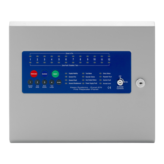
Page 20: Operating
OPERATING PANEL CONTROLS & INDICATIONS Zonal Fire Indicator LEDs Zones in Fire Zones In Fault, Zones Disabled or Zones In Test Indicator LEDs Zone Fault / Disabled / Test Suppl y Healthy Test Mode Delay Status RESOUND SILENCE RESET General Fire Sounder Status Repeater Fault General Fault... - Page 21 OPERATING Status LED Indicators LED On LED Pulsing Zones in Fire 1 - 12 Indicates alarm condition in zone. Zone Fault/Disabled/Test Indicates zone circuit is disabled or in test Indicates a fault in the zone circuit. 1 - 12 mode. Indicates mains and/or battery supply is Supply Healthy: present.
-
Page 22: Disable Mode
OPERATING DISABLE MODE Disable Mode is used to disable or isolate individual zone circuits or all sounder circuits, all auxiliary outputs and any delays to outputs. To initialise Disable Mode firstly activate the controls by turning RESOUND SILENCE RESET the key switch or by entering the four digit code. Then press and hold the Disable Mode button (1) for 3 seconds. -
Page 23: Test Mode
OPERATING TEST MODE Test Mode is used when testing the fire alarm system. In test mode the devices in the zone(s) in test, detectors and call points etc, can be activated and the panel will automatically reset, enabling the system to be tested by one person. - Page 24 www.haes-systems.com...
Need help?
Do you have a question about the ESENTO 12 and is the answer not in the manual?
Questions and answers