Table of Contents
Advertisement
Quick Links
AVTECH
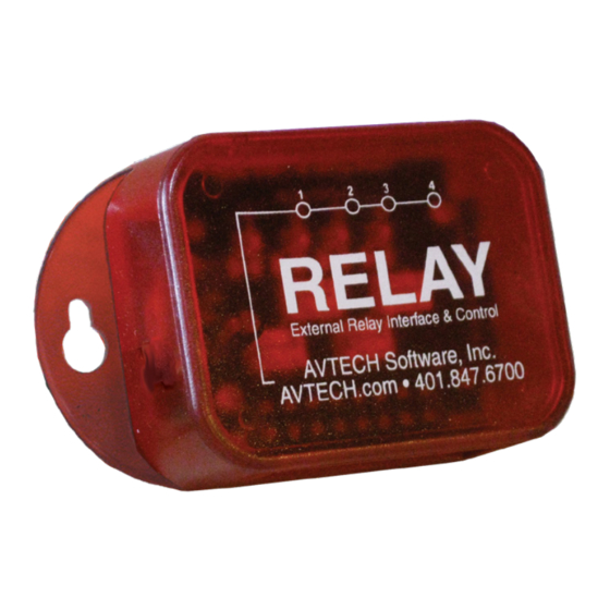
AVTECH's Relay Switch turns on and off up to 4 electrical
devices. You may individually control each of the 4 relay
outputs separately.
Relay Switch Package Contents
•
One (1) Relay Switch
•
Two (2) mounting screws
Relay Switch
Install Your Relay Switch
Do not use this sensor in hazardous (classified) locations or life safety applications.
Step 1: Mount your Relay Switch.
Mount your Relay Switch with screws through the flange holes, secure it with Velcro or
simply place it on a flat surface.
Step 2: Connect your Relay Switch to AVTECH's Light Tower & Relay Adapter.
To use your sensor with Room Alert 32S and 12S or Room Alert 32E, 12E and 3E, you
need AVTECH's Light Tower & Relay Adapter (LT-32-ADP), shown here.
To use your Relay Switch with the Room Alert 4E model, connect it directly to the Room
Alert 4E's custom port.
AVTECH Software, Inc.
Custom
Cord
Connect the Relay Switch's built-in custom cable to the
custom port on the Light Tower & Relay Adapter.
For more information about
AVTECH's Light Tower & Relay
Adapter, please see its Installation
Note, visit
your Product Specialist.
Temperature & Environment Monitoring... Made Easy!
Relay Switch
Relay
Ports
Front
AVTECH.com
or contact
AVTECH.com
Advertisement
Table of Contents

Related Manuals for Avtech RMA-RELAY-SEN

Summary of Contents for Avtech RMA-RELAY-SEN
- Page 1 Mount your Relay Switch with screws through the flange holes, secure it with Velcro or simply place it on a flat surface. Step 2: Connect your Relay Switch to AVTECH’s Light Tower & Relay Adapter. To use your sensor with Room Alert 32S and 12S or Room Alert 32E, 12E and 3E, you need AVTECH’s Light Tower &...
- Page 2 Step 3: Connect a low-voltage device to your Relay Switch. Disconnect power to the electrical device before beginning. Do not connect the relay outputs on AVTECH products to live circuits of over 125VAC or 24VDC. Use an appropriate wire to connect the relay ports to your electrical device; consult an electrician if you are unsure if the wire is compatible with the electrical load or device.
- Page 3 Relay Switch Sensor (RMA-RELAY-SEN) Previous Generation Relay Switch Please note that the previous generation of the Relay Switch operates differently than the current generation. In the previous generation model, shown below, you can individually control the first three relay outputs; the fourth is automatically activated when any one of the other outputs is on, allowing notification to a security panel.
- Page 4 Room Alert web interface. Both AVTECH’s Light Tower and AVTECH’s Relay Switch may be configured on this page. Depending on your model, the options you see in your Room Alert may vary slightly from those shown in the screenshots in this section.
- Page 5 Your Room Alert will automatically reboot and commit your changes. See next page for how to manually toggle your Light Tower or Relay from your Room Alert’s Status page. AVTECH Software, Inc. Page 5 AVTECH.com...
- Page 6 1st relay on the Relay Switch manually toggled on. Room Alert “S” models require you to log in with your device’s username and password before you can manually toggle. AVT-200610 AVTECH Software, Inc. Page 6 AVTECH.com...
Need help?
Do you have a question about the RMA-RELAY-SEN and is the answer not in the manual?
Questions and answers