Table of Contents
Advertisement
Advertisement
Table of Contents

Related Manuals for Hoymiles HM-250


Summary of Contents for Hoymiles HM-250
- Page 1 Version 1.1 (June 2020)
- Page 2 About the Manual This manual contains important instructions for the HM-250/HM-300/HM-350/HM-400 Microinverter and must be read in its entirety before installing or commissioning the equipment. For safety, only qualified technician, who has received training or has demonstrated skills can install and maintain this Microinverter under the guide of this document.
-
Page 3: Table Of Contents
6.4 Routine Maintenance ..........................20 6.5 Replace Microinverter ..........................21 7. Decommissions ..............................22 7.1 Decommissions ............................22 7.2 Storage and Transportation ........................22 7.3 Disposal ..............................23 8. Compliance Consideration ..........................23 © 2019 Hoymiles Converter Technology Co., Ltd. All rights reserved. - Page 4 Appendix 1: ................................27 Installation Map ..............................27 Appendix 2: ................................28 WIRING DIAGRAM – 230VAC SINGLE PHASE: ..................28 WIRING DIAGRAM – 230VAC / 400VAC THREE PHASE: ............... 29 © 2019 Hoymiles Converter Technology Co., Ltd. All rights reserved.
-
Page 5: Important Notes
The reader should stop, use caution and fully understand the operations explained before proceeding. 2. About Safety 2.1 Important Safety Instructions The HM-250/HM-300/HM-350/HM-400 Microinverter is designed and tested according to international © 2019 Hoymiles Converter Technology Co., Ltd. All rights reserved. -
Page 6: Explanation Of Symbols
Ø Do not use the equipment if any operating anomalies are found. Avoid temporary repairs. Ø All repairs should be carried out using only qualified spare parts, which must be installed in accordance with their intended use and by a licensed contractor or authorized Hoymiles service representative. -
Page 7: Radio Interference Statement
2) Increase the separation between the microinverter and the receiving antenna. 3) Place the shield between the microinverter and the receiving antenna, such as metal / concrete roof. 4) Contact your dealer or an experienced radio/TV technician for help. © 2019 Hoymiles Converter Technology Co., Ltd. All rights reserved. -
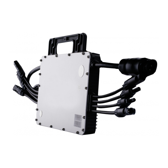
Page 8: About Product
“The world’s First Daisy-Chain Single Unit Microinverter” with extremely wide DC input operating voltage range (16-60V) and low start-up voltage (22V only). Hoymiles Single unit Microinverter HM-250/HM-300/HM-350/HM-400 is the perfect selection for PV system with uneven number of panels with world’s NO.1 CEC weighted efficiency – 96.50% (peak efficiency 96.70%) in 2015. -
Page 9: Dimension(Mm)
The current condition is contradicted with Microinverter operating requirement. No house loads or the Export control value has been set as “0” on the DTU under the Zero Export Control mode. © 2019 Hoymiles Converter Technology Co., Ltd. All rights reserved. -
Page 10: About Installation
Please install the Microinverter and all DC connections under the PV module to avoiding direct sunlight, rain exposure, snow layup, UV etc. Allow a minimum of 2 cm of space around the microinverter enclosure to ensure ventilation and heat dissipation. © 2019 Hoymiles Converter Technology Co., Ltd. All rights reserved. -
Page 11: Space Distance Required
Installation of the equipment is carried out based on the system design and the place in which the equipment is installed. The installation must be carried out with the equipment disconnected from the grid (power disconnect switch open) and with the photovoltaic modules shaded or isolated. © 2019 Hoymiles Converter Technology Co., Ltd. All rights reserved. -
Page 12: Installation Steps
B) Fix the screw on the rail. C) Hang the microinverter on the screw (shown as picture below), and tighten the screw. The silver cover side of the microinverter should be facing the panel. © 2019 Hoymiles Converter Technology Co., Ltd. All rights reserved. - Page 13 B) Install the AC end cap on the open AC connector of the last microinverter in the AC branch circuit. Step 3. Connect AC End Cable A) Make the end cable 1. Take the AC port apart into 3 parts: © 2019 Hoymiles Converter Technology Co., Ltd. All rights reserved.
- Page 14 C) Connect the other side of the AC End Cable to the distribution box, and wire it to the local grid network. Step 4. Create an Installation Map A) Peel the removable serial number label from each microinverter (The position of the label is shown as below.) © 2019 Hoymiles Converter Technology Co., Ltd. All rights reserved.
- Page 15 B) Affix the serial number label to the respective location on the installation map. Step 5. Connect PV Modules A) Mount the PV modules above the microinverter. B) Connect the PV modules’ DC cables to the DC input side of the microinverter. © 2019 Hoymiles Converter Technology Co., Ltd. All rights reserved.
-
Page 16: Troubleshooting
Hoymiles technical support. 1.Check if the grid configuration parameter is correct and upgrade again. Grid configuration 2. If the fault still exists, contact your dealer or Hoymiles technical parameter error support. 1. If the alarm occurs accidentally and the microinverter can still work Software error code normally, no special treatment is required. - Page 17 2. If the alarm occurs frequently, check whether the grid voltage is within the acceptable range. If no, contact the local power operator or change the grid overvoltage protection limit via Hoymiles monitoring system with the consent of the local power operator.
- Page 18 2. If the alarm occurs frequently, check whether the grid frequency change rate change rate is within the acceptable range. If no, contact the local power operator or change the grid frequency change rate limit via Hoymiles monitoring system with the consent of the local power operator. Power grid outage Please check whether there is a power grid outage.
-
Page 19: Status Led Indicator
Flashing Slow Green (4s gap): Producing power but there is no communication with DTU. ü Flashing Red (1s gap): Not producing power AC grid invalid (Voltage or frequency out of range). ü © 2019 Hoymiles Converter Technology Co., Ltd. All rights reserved. -
Page 20: On-Site Inspection (For Qualified Installer Only)
ü Flashing Red and Green alternately: Firmware is corrupted. *Note: All the faults are reported to the DTU, refer to the local APP of the DTU or Hoymiles Monitoring Platform for more information. 6.3 On-site Inspection (For qualified installer only) To troubleshoot an inoperable microinverter, follow the steps in the order shown. -
Page 21: Replace Microinverter
If all the microinverters connect to the DTU-Pro, the DTU can limit the output power imbalance of all the microinverters between phases to below 3.68kW if required. Please refer to “ Hoymiles Technical Note Limit Phase Balance ” for more details. -
Page 22: Decommissions
7.2 Storage and Transportation Hoymiles packages and protects individual components using suitable means to make the transport and subsequent handling easier. Transportation of the equipment, especially by road, must be carried out by suitable ways for protecting the components (in particular, the electronic components) from violent, shocks, humidity, vibration, etc. -
Page 23: Disposal
An external indication of earth fault alarm can be provided by the connecting the PV System to Hoymiles monitoring app/portal. For details of how to configure monitoring please refer to document “HMP Operating Guide (Webpage) V2.0” and “HMP Operation Guide (APP)”. -
Page 24: Technical Data
The output DC power of PV module is NOT recommended to exceed 1.35 times the output AC power of the microinverter. Refer to “Hoymiles Warranty Terms & Conditions” for more information. © 2019 Hoymiles Converter Technology Co., Ltd. All rights reserved. -
Page 25: Dc Input
Ambient temperature range (℃) -40 ~ +65 Storage temperature range (℃) -40 ~ +85 Dimensions (W×H×D mm) 182×164×29.5 Weight (kg) 1.98 Enclosure rating Outdoor-NEMA (IP67) Cooling Natural convection – No fans Altitude <2000m © 2019 Hoymiles Converter Technology Co., Ltd. All rights reserved. -
Page 26: Features
12 years standard, 25 years optional VDE-AR-N 4105:2018, EN50549-1:2019, VFR2019, Compliance AS 4777.2:2015, IEC/EN 62109-1/-2, IEC/EN 61000-3-2/-3, IEC/EN-61000-6-1/-2/-3/-4 *Note: Voltage and frequency ranges can be extended beyond nominal if required by the utility. © 2019 Hoymiles Converter Technology Co., Ltd. All rights reserved. -
Page 27: Installation Map
HM-250/HM-300/HM-350/HM-400 Appendix 1: Installation Map © 2019 Hoymiles Converter Technology Co., Ltd. All rights reserved. -
Page 28: Wiring Diagram - 230Vac Single Phase
HM-250/HM-300/HM-350/HM-400 Appendix 2: WIRING DIAGRAM – 230VAC SINGLE PHASE: © 2019 Hoymiles Converter Technology Co., Ltd. All rights reserved. -
Page 29: Wiring Diagram - 230Vac / 400Vac Three Phase
HM-250/HM-300/HM-350/HM-400 WIRING DIAGRAM – 230VAC / 400VAC THREE PHASE: © 2019 Hoymiles Converter Technology Co., Ltd. All rights reserved.
Need help?
Do you have a question about the HM-250 and is the answer not in the manual?
Questions and answers