
Related Manuals for LifeSafety Power FLEXPOWER NetLink NL2


Summary of Contents for LifeSafety Power FLEXPOWER NetLink NL2
- Page 1 Netlink® Communication Modules Installation and Operation LifeSafety Power, Inc. | PH 888.577.2898 | TechSupport@LifeSafetyPower.com P03-37 Rev A12...
-
Page 2: Table Of Contents
Netlink Installation and Operation Manual Table of Contents Notes and Warnings . . . . . . . . . . . . . . . . . . . . . . . . . . . . . . . . . . . . . .iii Symbol Definitions . -
Page 3: Notes And Warnings
Notes and Warnings Symbol Definitions Regulatory Information The following symbols are used throughout this manual The following equipment discussed within this manual has been tested to the following standards: This symbol is intended to alert the installer of • UL 294, UL 603, UL 1076 shock hazards within the enclosure . -
Page 4: Introduction
. Internal temperature is also sensed, and the NL4 and NLX also include a 6 foot external temperature probe for monitoring room temperature . The NL2 and NL4 provide two outputs for controlling external equipment using LifeSafety Power’s RB series of relays . -
Page 5: Section 1 - Installation
1 .1 Mounting the Netlink Communication Module Use the following procedure when mounting the Netlink module to a LifeSafety Power enclosure . 1 . Locate the appropriate mounting holes in the enclosure and snap the four standoffs provided into the holes . -
Page 6: Netlink Network Communication Module Overview
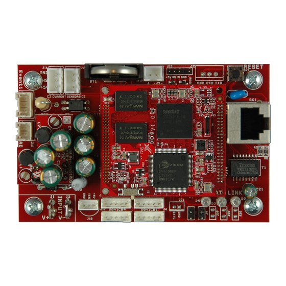
Netlink Installation and Operation Manual 1 .2 Netlink Network Communication Module Overview Device 3 Device 2 Device 1 Reset Device 4 Reset Event 1 Event 1 RJ45 ... - Page 7 Installation and Operation Temp Reset Battery DATA LINK RJ45 Event 1 Event1 Input Invert Jumper (J8) Enable 100Mbps (J19) This jumper inverts the action of the Event 1 Input . See sec- If present, this jumper enables 100Mbps speed for the net- tion 1 .3 .5 work connection .
- Page 8 Netlink Installation and Operation Manual Current Sensor Cable Current Sensor - Current Lead 1 (Short) The short orange lead connects in-line with the current to be measured toward the more negative side of the current flow . Positive current is measured when current flows from Current Lead 2 (Long Lead) to Current Lead 1 (Short Lead) .
-
Page 9: Connecting The Netlink Network Communication Module
Figure 1 .3, above) . If the device being connected to the Net- plied by an NS2 board, which is sold separately . See Ap- link uses the old-style connector, contact LifeSafety Power pendix 2 for more information . for an adaptor cable (bottom drawing in Figure 1 .3, above) . - Page 10 Netlink Installation and Operation Manual primary connection Netlink Input V+ V- V- alternate connection (only FPO150-250 models) Figure 1.4 - Power the Netlink from the FPO V+/V- or DC1 terminals Netlink FPO 1 Input Figure 1.5 - Do not power from another accessory board's output Note: NL2/NL4 shown - NLX Similar .
- Page 11 Installation and Operation 1.3.4 Connecting the Current Sensor(s) 1.3.5 Connecting the Event Input Typically, the current sensor is used to measure battery dis- Connect one end of the Event cable to the Event1 connector charge current to allow battery testing and utilization of the on the Netlink board and cut off the connector at the other Battery Condition bar graph .
- Page 12 LifeSafety Power's RB Series, supply the ground side to in the area in which it is installed .
- Page 13 Installation and Operation 1.3.9 RS485 Port (NLX only) The next device in the chain should connect from the sec- ond set of RS485 terminals on the monitored device to the The RS485 port allows connection of up to 16 additional next device in the chain and so on .
-
Page 14: Section 2 - Initial Configuration
Netlink Installation and Operation Manual Section 2 – Initial Configuration Before connecting the NetLink to a network for the first time, the board must be configured using a laptop . Unless otherwise specified, all screens shown are of the NL4 GUI . NL2 and NLX screens are similar, with changes as noted in the text . If using DHCP, a Network Scan Tool used for finding LSP devices is available at http://www .lifesafetypower .com/support/software- firmware-downloads . - Page 15 Depending on the firmware revision, the Netlink may default to DHCP after reboot . If a DHCP server is found, an IP address will be Netlink assigned . The LifeSafety Power scan software, or a third party software must then be used to find the IP address of the Figure 2.2 The Netlink Login Window (May appear different, depending on browser)
- Page 16 Netlink Installation and Operation Manual Figure 2.3 - Typical NL2 / NL4 Home Page (NL4 Shown)
- Page 17 Installation and Operation Figure 2.4 - Typical NLX Home Page 2.2.2 Configuring the TCP/IP Settings In the menu bar at the top of the browser screen (Figure 2 .4 .1 and 2 .4 .2), click the "Configure" link . In the TCP/IP Settings block of the Configuration screen (See Figure 2 .5 - next page), set the TCP/IP settings to the desired values for the network to which the NetLink will be connected .
- Page 18 Netlink Installation and Operation Manual 2.2.3 Time Settings The Time Settings block (See Figure 2 .5) is where the time and date are programmed into the Netlink . First, select the correct time zone from the drop down list and click Submit . After the time zone is set, the time and date can be set one of three ways: Manual Entry Enter the correct time and date in the following format and click the "Submit"...
- Page 19 Installation and Operation 2.2.5 Configuring the SNMP Settings Scrolling down in the Configure page reveals the "SNMP Settings" section (Figure 2 .6) . Figure 2.6 - Typical Configure Page (upper-middle portion) In the SNMP Setting block, under the "Basic" heading, set Read and Write Community to "public" and set Location to a meaningful name of your choice .
- Page 20 Netlink Installation and Operation Manual 2.2.6 Configuring the Email Settings The Netlink can be configured to send email alerts on user-specified conditions and periodic status reports . Underneath the SNMP Settings block on the Configure page is the Email Settings block (See Figure 2 .6) . Under "Receive Addresses", the email address or addresses to receive the alerts and reports should be entered .
-
Page 21: Configuring The Netlink
Installation and Operation 2.2.9 Configuring the Netlink Network Module Settings Below the VPN Settings block is the Network Module Settings block, where application-specific parameters of the Netlink can be set (See Figure 2 .7) . Client ID Enter any meaningful name to help identify the site or customer . The Client ID will appear at the top of the home page . - Page 22 Netlink Installation and Operation Manual Figure 2.7 - Typical Configure Page (lower-middle portion) 2.2.10 Current Sensor Calibration In this block, any connected current sensors can be calibrated by selecting the current sensor to calibrate and clicking the "Zeroing" button . Ensure both high current leads of the current sensor are disconnected and the white data cable is connected before clicking the Zeroing button .
- Page 23 Installation and Operation After selecting the Authorization level, enter the new user name in the User Name column and enter the password into the Password column . Passwords must meet the complexity level setting requirements . Re-enter the password into the Verify Password column . After clicking Submit, the new user will be active and another blank row will appear for entering the next user name .
- Page 24 Netlink Installation and Operation Manual 2.2.17 User Login Record Click the Show Login Log button to show the history of login information for the Netlink board . See Figure 2 .9 Figure 2.9 - Typical Configure Page (bottom portion) Figure 2.10 - Import Settings Page...
- Page 25 Installation and Operation 2.2.18 User Activity Record Clicking the "Show Activity Log" button will show a time and date-stamped log of all user activity . 2.2.19 Setting up the Parameters for the Email Reports The Netlink can send email alerts based on selectable conditions . If enabled, when the selected conditions are met, the Netlink will send an email with an attached report file (in CSV format) .
- Page 26 Netlink Installation and Operation Manual Figure 2.11 - Typical Reporting Page...
-
Page 27: Section 3 - Using The Netlink
Installation and Operation Section 3 – Using the NETLINK Board Before system parameters can be viewed, you must be logged into the Netlink board using the proper IP address, user name, and password for the Netlink, as shown in Section 2 of this manual . Unless otherwise specified, all screens shown are of the NL4 . - Page 28 Netlink Installation and Operation Manual 3.1.1 Basic Site Information The top portion of the Netlink Home page lists the Client ID and Site ID (as programmed on the Configure page) as well as the system time and date (Figure 3 .1) . The Site ID field will be green if there are no faults or service alerts detected . This field will turn yellow on any fault condition or blue on any service alert conditions .
-
Page 29: Accessing And Programming Connected Devices
Installation and Operation 3 .2 Accessing and Programming Connected Devices When devices are connected to the Netlink, detailed information relating to these devices may be viewed and various parameters can be programmed through the Netlink's interface . Note that programming these parameters changes the operation of the device itself . To access the page for a device, click on the device in the Netlink Connected Devices section of the home page . - Page 30 Netlink Installation and Operation Manual 3.2.1.2 Power System Monitoring & System History Any power supply connected to a device input will provide the following parameters (Figure 3 .2): Device ID This is the identifying label for the device . The FP-1 through FP-12 label is given by the Netlink and is not user settable .
- Page 31 Installation and Operation 4 Green Bars Battery is at 80% to 100% charge 3 Green Bars Battery is at 60% to 79% charge 2 Green Bars Battery is at 40% to 59% charge 1 Green Bar Battery is at 20% to 39% charge 1 Yellow Bar Battery is at 6% to 19% charge (email alert will be sent, if enabled) 1 Red Bar...
- Page 32 Netlink Installation and Operation Manual tion (See Figure 3 .5) • At the conclusion of the test, the measured battery runtime and last test date will be displayed in the Battery Test section (See Figure 3 .6) . The results will also be emailed if emailing is enabled . To Schedule a Test •...
- Page 33 Installation and Operation Figure 3.5 - Battery Test in Progress Figure 3.6 - Battery Test Results...
- Page 34 Netlink Installation and Operation Manual 3.2.1.6 Power Supply Settings The power supply section shows the programmable settings for the power supply . The following parameters are available: Battery Charge Selector Select the proper battery size range for optimal charging rate . AC Fault Reporting Delay Select the desired delay for reporting an AC fault in hours, minutes, and seconds .
- Page 35 Installation and Operation Figure 3.7 - Typical Power Supply Page (bottom portion)
-
Page 36: Using The Tools Page
Netlink Installation and Operation Manual 3 .3 Using the Tools Page Clicking the Tools link at the top of the display will bring up the Tools page (See Figure 3 .8) . This page allows upgrading of the firmware and rebooting the Netlink board . Figure 3.8 - The Tools Page Upgrading Firmware The Upgrade Firmware section is at the top left of the Tools page (See Figure 3 .8) . -
Page 37: Understanding The Email Report
Installation and Operation 3 .4 Understanding The Email Report The report file sent by email by the Netlink is sent as an unformatted .CSV file . Many programs, such as Microsoft Excel, will import a .CSV file to allow viewing of the data (See Figure 3 .9) . Note that the fields included will vary depending on the specific system and which parameters are selected on the Reporting page . -
Page 38: Appendix 1 - Software Agreement
Upgrade the Software subject to Upgrades that may be provided from time-to-time ING BUT NOT LIMITED TO NON-INFRINGEMENT OF THIRD PARTY RIGHTS, TITLE, by LIFESAFETY POWER INC . at its sole discretion . The Software, subsequent to any INTEGRATION, INTEROPERABILITY, ACCURACY, SECURITY, AVAILABILITY, SATIS-... - Page 39 (i) Interpretation and Construction . The parties agree that the terms of this AGREEMENT (b) Further Limitations . IN NO EVENT WILL LIFESAFETY POWER INC . OR ANY OF ITS result from negotiations between them . This AGREEMENT will not be construed in OFFICERS, DIRECTORS, SHAREHOLDERS, PARENTS, SUBSIDIARIES, AGENTS, IN- favor of or against either party by reason of authorship .
-
Page 40: Appendix 2 - Ns2 Board
A2 .1 Mounting the NS2 Output Controller Accessory Use the following procedure when mounting an NS2 Output Controller Accessory to a LifeSafety Power enclosure . 1 . Locate the appropriate mounting holes in the enclosure and snap the four standoffs provided into the holes . - Page 41 . Typically, these are connected to the B1 and B2 The voltages indicated are not accurate and are only for inputs of the A8 distribution boards in a LifeSafety power indication of presence of voltage . Place jumper J9 on FPA system .
- Page 42 Netlink Installation and Operation Manual A2 .3 Wiring the NS2 1.3.8 NetLink Power Connection In an AC system, power to the Netlink board MUST be supplied by an NS2 board, which is sold separately . The NS2 board converts the AC power from the low voltage transformer to DC voltage for powering the Netlink board . (Figure A2 .2) Use the cable with the three pin connector at one end and two faston connectors at the other end to make the connection .
- Page 43 Installation and Operation...
- Page 44 Conditions of Sale for this product, and in no case will LifeSafety Power or its distributors be liable for any incidental, indirect, or consequential damages arising from the sale, resale, use, or misuse of the product. Specifications are subject to change without notice.
Need help?
Do you have a question about the FLEXPOWER NetLink NL2 and is the answer not in the manual?
Questions and answers