
Related Manuals for LifeSafety Power FlexPower C4


Summary of Contents for LifeSafety Power FlexPower C4
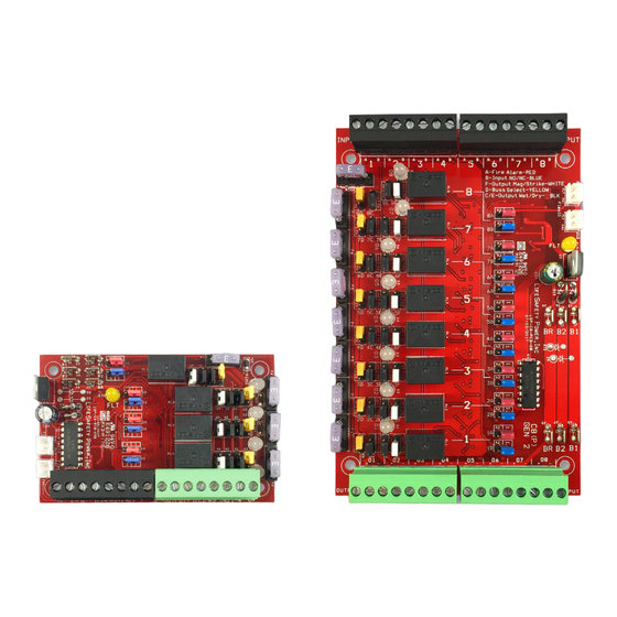
- Page 1 C4/C4P, C8/C8P Installation Manual LifeSafety Power, Inc. | PH 888.577.2898 | TechSupport@LifeSafetyPower.com P03-006 Rev A15...
-
Page 2: Table Of Contents
C4,C4P / C8, C8P Installation Manual Table of Contents Regulatory Information Description . . . . . . . . . . . . . . . . . . . . . . . . . . . . . . . . . . . . .1 The equipment discussed within this manual has been tested to the following standards: Specifications . -
Page 3: Power Control Accessory Overview
Power Control Accessory Overview Important: Note Jumper Position Orientation FAULT FAULT C4/C4P JUMPER PROGRAMMING Reference Jumper Color IN1A IN1B IN2A IN2B IN3A IN3B IN4A IN4B INVERT input BLUE C&E WET/DRY output INPUT FIELD WIRING 1–4 OUTPUT FIELD WIRING 1–4 BLACK... - Page 4 C4,C4P / C8, C8P Installation Manual Jumper B - BLUE (Input Invert) a soldered-in PTC . Fuses or PTCs are not in the circuit when This jumper is used to select a fail-safe or fail-secure input . the zone is configured as a relay contact output . Adjust this jumper so that the zone's output LED is FLASH- ING when the door is unlocked .
-
Page 5: Connecting The Power Control Modules
Connecting the Power Control Module Remove all AC and battery power from the FPO system before adding or replacing a power control board. Each of the B1, B2, BR, and FlexIO busses has two connectors. These connectors may be used interchangeably. Required Connections For example: FlexIO from the power supply may be connected Optional Connections... - Page 6 C4,C4P / C8, C8P Installation Manual Diode Removal Reverse Protection Diodes The outputs of the C4/C4P/C8/C8P have built-in reverse protection diodes . If a delay in lock release is present or if the zone is C4 output diodes being used as a dry contact output, the diode from that zone may be removed from the circuit as shown below . Only remove the diodes from outputs requiring their removal! underside of board C8/C8P Diode Removal...
-
Page 7: Input And Output Wiring
Input and Output Wiring INPUT WIRING Each input on the C4/C4P and C8/C8P has an “A” terminal and a “B” terminal . • When using a relay contact to activate the input, the contact is placed across these terminals . It is normal to measure a voltage across these terminals when set for C4/C4P a relay contact input . -
Page 8: Common Jumper Settings
C4,C4P / C8, C8P Installation Manual Common Jumper Settings Jumper (red) (blue) (black) (yellow) (black) (white) Continuous Auxiliary Output (No zone control input) With FAI Note 1 Without FAI Note 1 Maglock Output NC Contact Input - with FAI Note 1 NC Contact Input - without FAI Note 1 NO Contact Input - with FAI... -
Page 9: C4/C4P Application Example
C4/C4P Application Example Note: For UL Compliance, any locking device shall be configured for fail safe operation upon occurrence of an alarm as shown with a normally closed relay contact B1 24V 1F 1E B2 12V 2F 2E 2C 2D FAULT FAULT 3F 3E 3C 3D... -
Page 10: C8/C8P Application Example
C4,C4P / C8, C8P Installation Manual C8/C8P Application Example Note: For UL Compliance, any locking device shall be configured for fail safe operation upon occurrence of an alarm as shown with a normally closed relay contact NO Contact Open Collector (Transistor) In Open Collector (Transistor) In NC Contact NC Contact... - Page 11 C8/C8P Application Example - continued Zone 1 Zone 7 24V Mag Lock Output, Voltage Input, with FAI NO Relay Contact Output, Open Collector (transistor) In- put, with FAI This zone shows a typical 24V Mag Lock application, using a voltage input on the zone . The door will unlock upon an This zone shows a NO relay contact output using an open FAI signal being received from the FPO Power Supply .
- Page 12 C4,C4P / C8, C8P Installation Manual FlexPower System Replacement Parts Board Kits Order # Description FPO250 A01-007 FPO250 replacement board FPO150 A01-005 FPO150 replacement board FPO75 A01-003 FPO75 replacement board B100 A03-009 DC-DC Converter (12VDC or adjustable 5 to 18VDC) replacement board A02-001 Simple distribution replacement board A02-002...
- Page 13 THIS PAGE LEFT BLANK...
- Page 14 Conditions of Sale for this product, and in no case will LifeSafety Power or its distributors be liable for any incidental, indirect, or consequential damages arising from the sale, resale, use, or misuse of the product. Specifications are subject to change without notice.
Need help?
Do you have a question about the FlexPower C4 and is the answer not in the manual?
Questions and answers