Table of Contents
Advertisement
Quick Links
Gas Analysis
Sample gas probes
GAS 222.31 Ex2
Installation and Operation Instructions
Original instructions
BE460052
Bühler Technologies GmbH, Harkortstr. 29, D-40880 Ratingen
08/2019
Tel. +49 (0) 21 02 / 49 89-0, Fax: +49 (0) 21 02 / 49 89-20
E-Mail: analyse@buehler-technologies.com
Internet: www.buehler-technologies.com
Advertisement
Table of Contents

Subscribe to Our Youtube Channel
Related Manuals for Buhler GAS 222.31 Ex2


Summary of Contents for Buhler GAS 222.31 Ex2
- Page 1 Gas Analysis Sample gas probes GAS 222.31 Ex2 Installation and Operation Instructions Original instructions BE460052 Bühler Technologies GmbH, Harkortstr. 29, D-40880 Ratingen 08/2019 Tel. +49 (0) 21 02 / 49 89-0, Fax: +49 (0) 21 02 / 49 89-20 E-Mail: analyse@buehler-technologies.com...
- Page 2 Bühler Technologies GmbH, Harkortstr. 29, D-40880 Ratingen Tel. +49 (0) 21 02 / 49 89-0, Fax: +49 (0) 21 02 / 49 89-20 Internet: www.buehler-technologies.com E-Mail: analyse@buehler-technologies.com Read this instruction carefully prior to installation and/or use. Pay at- tention particularly to all advises and safety instructions to prevent in- juries.
-
Page 3: Table Of Contents
GAS 222.31 Ex2 Table of Contents Introduction............................................. 2 Intended Use......................................... 2 Type Plate.......................................... 2 Contents.......................................... 2 Ordering instructions ...................................... 3 Product Description...................................... 4 Safety instructions......................................... 5 Important Information...................................... 5 General Hazard Warnings .................................... 6 Special conditions for safe use .................................. 7 Ambient Temperature range of the equipment............................ 7 Transport and storage ........................................ -
Page 4: Introduction
GAS 222.31 Ex2 1 Introduction 1.1 Intended Use The sample gas probe is intended for installation into gas analysis systems in commercial applications. It may be operated in a Zone 2, explosion class IIC, explosive gas atmosphere which is rarely and only temporarily explosive. Zone 2 explosive gas atmospheres may be extracted with or transported with these probes. -
Page 5: Ordering Instructions
GAS 222.31 Ex2 1.4 Ordering instructions The item number is a code for the configuration of your unit. Please use the following model key: 4622231 X 0 X X X X 3 X X X X X X X Product Characteristics... -
Page 6: Product Description
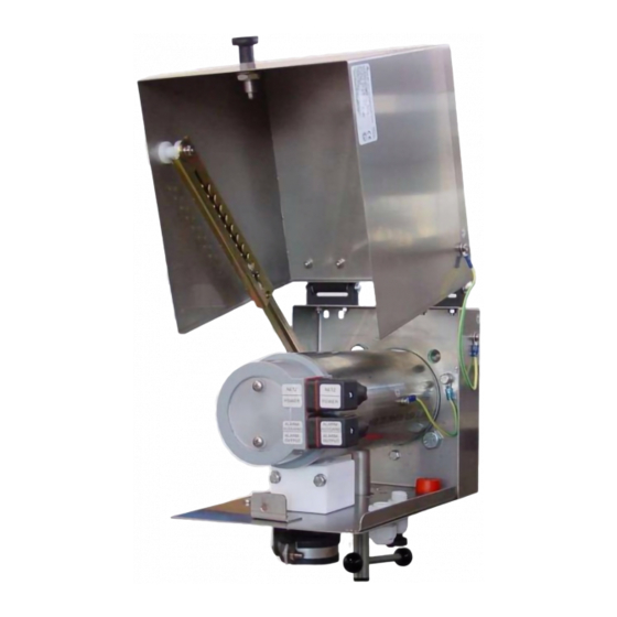
GAS 222.31 Ex2 1.5 Product Description The probe is equipped with self-regulating PTC heating cartridges and a temperature contact. Probe Description GAS 222.31 Ex2 Probe with inlet filter, shut-off valve and blowback connection GAS 222.31-JB Ex2 Probe with inlet filter, shut-off valve, blowback connection and terminal box... -
Page 7: Safety Instructions
GAS 222.31 Ex2 2 Safety instructions 2.1 Important Information This unit may only be used if: – the product is being used under the conditions described in the operating- and installation instructions, used according to the nameplate and for applications for which it is intended. any unauthorized modifications to the device will void the war- ranty provided by Bühler Technologies GmbH,... -
Page 8: General Hazard Warnings
GAS 222.31 Ex2 2.2 General Hazard Warnings The maximum surface temperature of the probes solely varies by operating conditions (steam temperature, sample gas inlet temperature, ambient temperature, fluid flow rate). For use in explosive areas please particularly note the related hazard warn- ings. -
Page 9: Special Conditions For Safe Use
GAS 222.31 Ex2 DANGER Explosion hazard Life and explosion risk may result from gas leakage due to improper use. a) Use the devices only as described in this manual. b) Regard the process conditions. c) Check tubes and hoses for leakage. -
Page 10: Transport And Storage
GAS 222.31 Ex2 3 Transport and storage Only transport the product inside the original packaging or a suitable alternative. The equipment must be protected from moisture and heat when not in use. They must be stored in a covered, dry and dust-free room at a temperature between -20 °C to 50 °C (-4 °F to 122 °F). -
Page 11: Installation And Connection
GAS 222.31 Ex2 4 Installation and connection NOTICE Accessories may limit critical operating parameters of the base unit Adding accessories may limit critical operating parameters. Ambient temperatures, zone classifications, explosion groups, temperature classes or chemical resistances of ac- cessories may vary from the base unit. -
Page 12: Connecting The Gas Line
GAS 222.31 Ex2 4.5 Connecting the Gas Line The sample gas line must be carefully and properly connected using a suitable fitting. This table provides an overview of the sample gas probe connections: Probe Reservoir Ball valve Control valve GAS 222... -
Page 13: Connecting The Calibrating Gas Line (Optional)
GAS 222.31 Ex2 4.5.2 Connecting the calibrating gas line (optional) Connecting the calibrating gas line requires a Ø6 mm or Ø1/4” pipe fitting. If the calibrating gas connection was ordered with check valve, a Ø6 mm or Ø1/4” pipe can be connected directly to the check valve. -
Page 14: Version Without Terminal Box
GAS 222.31 Ex2 Only use cables with a temperature resistance of > 100 °C (212 °F) to connect to power. Make sure the connecting cable has suffi- cient strain relief (match cable diameter to the seal on the cubic plug/cable fitting). Please note, the heating system briefly has high starting currents (max. 6 A). Use a suitable fuse (8 A). When connecting, also ob- serve the applicable explosion protection regulations (e.g. -
Page 15: Limit Switch (Optional)
GAS 222.31 Ex2 DANGER Potential equalization/static charge Static charges can result in incendive sparking. Avoid static charges. All conductive probe parts must be earthed! The housing has a connection for an earth/equipotential bonding conductor. Ensure the housing is adequately earthed (minimum conductor cross-section 4 mm Particularly also observe the requirements of IEC/EN 60079-14! 4.7.6 Limit Switch (Optional) -
Page 16: Operation And Control
GAS 222.31 Ex2 5 Operation and Control NOTICE The device must not be operated beyond its specifications. NOTICE The weather hood must be closed during operation! WARNING Housing or component damage Never exceed the maximum working pressure and temperature range of the drive. -
Page 17: Maintenance
GAS 222.31 Ex2 6 Maintenance – Damaged parts must be replaced immediately. – Regularly check the function of the electrical protection. During maintenance, remember: – The equipment must be maintained by a professional familiar with the safety requirements and risks. -
Page 18: Maintaining The Filter Element
GAS 222.31 Ex2 CAUTION Drive pressurised Never loosen or remove the cover or any accessories with the drive pressurised. CAUTION Never open the drive with the function “single-acting”! This may only be done at the manufacturer’s plant. CAUTION Do not attach levers or tools to the drive’s spindle! -
Page 19: Backwashing The Intake Filter (Within The Process Stream)
GAS 222.31 Ex2 6.2 Backwashing the Intake Filter (within the process stream) DANGER Adiabatic compression during gas blowback (explosion hazard)! Adiabatic compression may cause high gas temperatures and must be checked by the user. Gas blowback may result in high gas temperatures due to adiabatic compression. This can cause flammable gases to ignite spontaneously. -
Page 20: Maintenance Schedule
GAS 222.31 Ex2 6.3 Maintenance Schedule NOTICE When using the probe in explosive areas the maintenance schedule must be observed! Maintenance schedule for normal ambient conditions: Component Interval in operating Work to be performed To be performed by hours Entire probe every 8000 h –... -
Page 21: Service And Repair
GAS 222.31 Ex2 7 Service and repair This chapter contains information on troubleshooting and correction should an error occur during operation. Repairs to the unit must be performed by Bühler authorised personnel. Please contact our Service Department with any questions: Tel.: +49-(0)2102-498955 or your agent... -
Page 22: Disposal
GAS 222.31 Ex2 8 Disposal Dispose of parts so as not to endanger the health or environment. Follow the laws in the country of use for disposing of elec- tronic components and devices during disposal. 20 Bühler Technologies GmbH BE460052 ◦ 08/2019... -
Page 23: Appendices
GAS 222.31 Ex2 9 Appendices 9.1 Technical Data Gas Probe Technical Data Ambient temperature without accessories: -20 to +80 °C Ambient temperature for accessories: Component Ambient temperature range Compressed air valve: -30 °C < T < +60 °C Solenoid valve for pneumatic drive: -10 °C <... -
Page 24: Connection Diagram
GAS 222.31 Ex2 9.2 Connection Diagram Mains Insufficient temperature alarm Pin assignment Mains 115-230 VAC 400 W Heater Insufficient temperature alarm 30 V; 100 mA; (contact opens when the operating temperature is reached) Optionally with NO contact (contact closes when the operating temperature is reached) 9.3 Terminal Diagram Probe Terminal Box... -
Page 25: Terminal Diagram Terminal Box Limit Switch
GAS 222.31 Ex2 9.4 Terminal Diagram Terminal Box Limit Switch OPEN CLOSED The connection diagram shows the limit switch box in the intermediate position. Switches not actuated. 9.5 Flow chart BE460052 ◦ 08/2019 Bühler Technologies GmbH... -
Page 26: Dimensions
GAS 222.31 Ex2 9.6 Dimensions Bühler Technologies GmbH BE460052 ◦ 08/2019... - Page 27 GAS 222.31 Ex2 BE460052 ◦ 08/2019 Bühler Technologies GmbH...
-
Page 28: List Of Chemical Resistance
GAS 222.31 Ex2 9.7 List of chemical resistance Materials of your device in contact with media are printed on the type plate. Formula Medium Concentration Teflon® FFKM Viton® PTFE COCH Acetone Benzol Chlorine 10 % wet Chlorine 97 % Ethane... -
Page 29: User Book (Please Make Copies)
GAS 222.31 Ex2 9.8 User book (Please make copies) Maintained on Unit no. Operating hours Remarks Signature BE460052 ◦ 08/2019 Bühler Technologies GmbH... -
Page 30: Attached Documents
GAS 222.31 Ex2 10 Attached Documents – Type Examination Certificate IBExU17ATEXB007X – Certificate IECEx IBE 17.0002X – Declaration of Conformity KX460030 – Accessories Data Sheet 461099 – RMA - Decontamination Statement Bühler Technologies GmbH BE460052 ◦ 08/2019... - Page 39 Gasentnahmesonde / Sample gas probe Typ / type: GAS 222.20 Ex2, GAS 222.21 Ex2 GAS 222.31 Ex2, GAS 222.35 Ex2 Die Produkte werden entsprechend der derzeitig gültigen Atex-Richtlinie innerhalb der internen Fertigungskontrolle folgendermaßen gekennzeichnet: The products are marked according to the currently valid Atex directive during internal control of production:...
- Page 40 Accessories for Sample Gas Probe GAS 222 § Downstream filters § Sample tubes § Capacitive vessel § In-situ filters § Cal gas connections § Pneumatic actuators § Extensions § Adapter flanges § 3/2-way-solenoid valves § Blowback controllers Page 2 - 4 Page 8 Page 5 - 7 For general information, see data sheet “Sample gas probes GAS 222”...
- Page 41 Sample tubes, in-situ filters and extensions § Various materials § Various dimensions § Heated or nonheated extensions Sample tube T max. Material Length Part No.: 1.4571 462220010300 600°C 300 mm X X X X X X X X X X X X X X 1.4571 500 mm...
- Page 42 Sample tubes, in-situ filters and extensions § Various materials § Various dimensions § Heated or nonheated extensions In-situ filter Material T max. Length Pore size Part No.: stainless steel 600°C 237 mm 5 µm 46222303 stainless steel 237 mm 0.5 µm 46222303F* 600°C Hastelloy...
- Page 43 Sample tubes, in-situ filters and extensions § Various materials § Various dimensions § Heated or nonheated extensions Protection shield Part No.: for in-situ filter 03 462223034 for in-situ filter 04 462223044 Extensions Material Mains voltage Length G3/4 nonheated 1.4571 4622230320200 X X X X X X X X X X X X...
- Page 44 Entnahmerohre / tubes Verlängerungen / extensions ø Unbeheizt / unheated var. G3/4 Тyp var. G3/4 G3/4 0,2-2 m G3/4 var. 21,3 G3/4 G1/2 0,25-1,5m G1/2 var. G3/4 var. G3/4 var. G3/4 ø 02-0,5 24 G3/4 36 Beheizt / heated 02-1,0 1000 24 G3/4 36 Тyp ø...
- Page 45 Blowback § With ball valve or solenoid valve § Heated or nonheated § Manuell or automatic contro Ambient Capacitive vessel Part No.: temperature PAV 01 46222PAV Accessories for capacitive vessel ball valve 46222PAVKH 2/2-way-MV 24VDC* -10 ... +55°C 46222PAVMV1 2/2-way-MV 110V 50Hz -10 ...
- Page 46 Details: A) Blowback Ordering note for capacitive vessel: For attachment to GAS 222.11 / 30 / 35-U, a support is required. Ordering note for pneumatic actuator: If a blowback controller is required, only actuator P/N 46222030 is possible. We advise the installation of a position indicator switch to control the pneumatic actuator. Integrated blowback controller in the probe controller In addition to the stand-alone blowback controller (RRS), an integrated blowback controller is optionally available...
- Page 48 Downstream filter elements and further options Downstream filter Part no.: Material O-Rings Pore size 46222026 Ceramics Viton 3 µm X X X X X X X X X X X X X X Ceramics 3 µm 46222026P X X X X X X X X X X X X X X...
- Page 49 RMA-Formular und Erklärung über Dekontaminierung RMA-Form and explanation for decontamination RMA-Nr./ RMA-No. Die RMA-Nummer bekommen Sie von Ihrem Ansprechpartner im Vertrieb oder Service./ You may obtain the RMA number from your sales or service representative. Zu diesem Rücksendeschein gehört eine Dekontaminierungserklärung. Die gesetzlichen Vorschriften schreiben vor, dass Sie uns diese Dekontaminierungserklärung ausgefüllt und unterschrieben zurücksenden müssen.
- Page 50 Dekontaminierungserklärung DE000011 Bühler Technologies GmbH, Harkortstr. 29, D-40880 Ratingen 01/2019 Tel. +49 (0) 21 02 / 49 89-0, Fax: +49 (0) 21 02 / 49 89-20 E-Mail: service@buehler-technologies.com Internet: www.buehler-technologies.com...
Need help?
Do you have a question about the GAS 222.31 Ex2 and is the answer not in the manual?
Questions and answers