Table of Contents
Advertisement
Quick Links
1131 WIRELESS RECESSED
CONTACT
Installation Guide
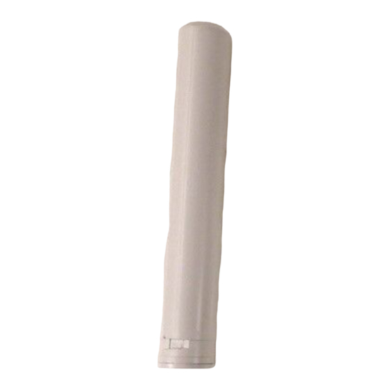
Figure 1: 1131 Recessed Contact
DESCRIPTION
The 1131 is a wireless recessed
contact that provides concealed
protection for doors, windows,
or any other application needing
a discreet contact. As with all
DMP 1100 Series transmitters,
the onboard LED provides
built‑in survey capability to allow
for single‑person installations,
eliminating the requirement
for an external survey kit. The
1131 transmits Normal, Alarm, and
Low Battery conditions.
•
All 1100 Series Wireless Receivers
and panels with built‑in 1100
Series Wireless Receivers
What is Included?
•
One 1131 Transmitter
•
One 1131MAG‑W Magnet
•
One 3 V Lithium
CR12600 Battery
1
PROGRAM THE PANEL
Refer to the panel programming guide as needed. After completing
each of the following steps, press CMD to advance to the next
prompt.
At a keypad, enter 6653 (PROG) to access the Programmer
1.
Menu.
2.
At ZONE INFORMATION, enter the wireless zone number.
3.
At *UNUSED*, enter the zone name.
At ZONE TYPE, press any select key or area and select the
4.
zone type.
5.
At AREA NO, enter the area number.
6.
At the NEXT ZN? prompt, select NO.
7.
When WIRELESS? displays, select YES.
At SERIAL#, enter the eight‑digit device serial number.
8.
9.
At SUPRVSN TIME, enter a supervision time. Default is 240.
10. At the NEXT ZN? prompt, select YES if you are finished
programming the zone. Select NO if you would like to access
additional programming options.
11. To save panel programming, go to STOP and press CMD.
2
INSTALL THE BATTERY
Use only 3.0 V lithium batteries, such as the Model CR12600.
1.
Insert a small screwdriver in the hole at the bottom of the
housing tube to push out the battery tray and PCB.
2.
Place the battery back into the battery tray with the
negative end of the battery facing the transmitter PCB.
3.
Slide the battery tray and PCB into the housing tube as
required for desired travel distance. Refer to Figure 2.
Travel Distance
Depending on PCB orientation, the distance that the door can
travel before a fault is indicated can be increased or decreased.
For areas where wood doors expand and contract seasonally, it
may be helpful to increase travel distance.
Note: The travel distance of sliding doors is 3/4" regardless of
the reed switch orientation.
3/4 Inch Travel Distance—Install the transmitter with the reed
switch on the top side of the PCB to allow a longer (3/4") distance
of travel.
3/8 Inch Travel Distance—Install the transmitter with the reed
switch on the bottom side of the PCB to allow a shorter (3/8")
distance of travel.
Advertisement
Table of Contents

Related Manuals for DMP Electronics 1131


Summary of Contents for DMP Electronics 1131
- Page 1 At ZONE TYPE, press any select key or area and select the zone type. DESCRIPTION At AREA NO, enter the area number. The 1131 is a wireless recessed At the NEXT ZN? prompt, select NO. contact that provides concealed When WIRELESS? displays, select YES.
- Page 2 Figure 2: Assembling the Housing SELECT A LOCATION The 1131 provides a Survey LED capability to allow one person to confirm communication with the wireless receiver or panel while the cover is removed. Move the magnet within 1/2 inch of the contact or pull it away from the contact to send data to the receiver.
- Page 3 Once the battery is replaced, a sensor reset is required at the keypad to clear the LOBAT message. On an LCD keypad, press and hold 2 for two seconds. On a graphic touchscreen keypad, press RESET. Enter your user code, if required. The keypad displays SENSORS OFF followed by SENSORS ON. 1131 INSTALLATION GUIDE DIGITAL MONITORING PRODUCTS...
- Page 4 établies par le Code de sécurité 6 de Santé Canada. Le système doit être installé à une distance minimale de 7.87 pouces (20 cm) séparant l’antenne d’une personne présente en conformité avec les limites permises d’exposition du grand public. 1131 WIRELESS Ordering Information 1131-W...
Need help?
Do you have a question about the 1131 and is the answer not in the manual?
Questions and answers