
Subscribe to Our Youtube Channel
Related Manuals for Campbell CM106BK

Summary of Contents for Campbell CM106BK
- Page 1 CM106BK Tripod Kit Revision: 10/19 Copyright © 2011 – 2019 Campbell Scientific, Inc.
- Page 2 Limited Warranty “Products manufactured by CSI are warranted by CSI to be free from defects in materials and workmanship under normal use and service for twelve months from the date of shipment unless otherwise specified in the corresponding product manual. (Product manuals are available for review online at www.campbellsci.com.) Products not manufactured by CSI, but that are resold by CSI, are warranted only to the limits extended by the original manufacturer.
- Page 3 Campbell Scientific company serves your country. To obtain a Returned Materials Authorization (RMA) number, contact CAMPBELL SCIENTIFIC, INC., phone (435) 227-9000. Please write the issued RMA number clearly on the outside of the shipping container. Campbell Scientific’s shipping address is: CAMPBELL SCIENTIFIC, INC.
- Page 4 Periodically (at least yearly) check electrical ground connections. • WHILE EVERY ATTEMPT IS MADE TO EMBODY THE HIGHEST DEGREE OF SAFETY IN ALL CAMPBELL SCIENTIFIC PRODUCTS, THE CUSTOMER ASSUMES ALL RISK FROM ANY INJURY RESULTING FROM IMPROPER INSTALLATION, USE, OR MAINTENANCE OF TRIPODS, TOWERS, OR ATTACHMENTS TO TRIPODS AND TOWERS SUCH AS SENSORS, CROSSARMS, ENCLOSURES, ANTENNAS, ETC.
-
Page 5: Table Of Contents
CM210 Crossarm Mounting Kit............20 CM216 Mast Mounting Kit ..............21 CM220 Right Angle Mounting Kit ............ 21 CMB200 Crossarm Brace Kit ............23 6.4.1 Overview ..................23 6.4.2 Components ................23 6.4.3 Assembly..................24 Appendix A. CM106BK Allowable Wind Speeds ....... A-1... - Page 6 Table of Contents Figures 1-1. Typical tripod-based weather station ...........1 5-1. Tripod component dimensions .............5 5-2. Tripod with one leg pointing downhill ..........9 5-3. Guy kit....................10 5-4. Leg attachment ................... 11 5-5. Center Duckbill Anchor Kit ............... 12 5-6. Staking the tripod feet ................
-
Page 7: Introduction
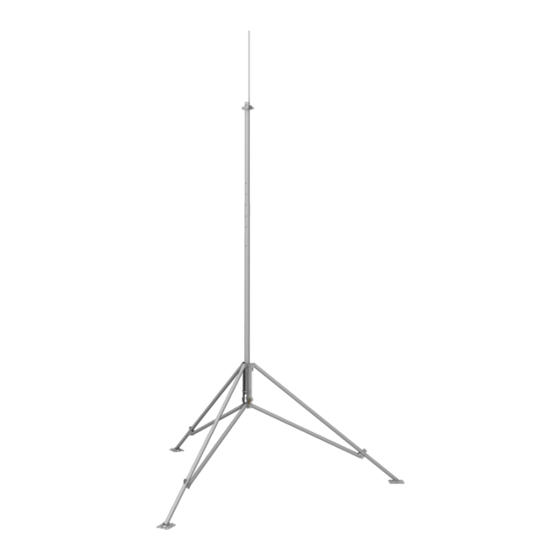
CM106BK Tripod Kit Introduction The CM106BK is a general purpose tripod that can be used for mounting sensors, solar panels, antennas, and instrument enclosures. The CM106BK is constructed from galvanized steel, with individually adjustable legs that allow installation over uneven terrain. Height of the mast is 3 m (10 ft). -
Page 8: Precautions
Initial Inspection Inspect Packaging Upon receiving the CM106BK, inspect the packaging and contents for damage. Claims for shipping damage must be filed with the shipping company. Locate the packing slip for the order and compare the items listed on the packing slip to the items that were actually shipped. -
Page 9: Tripod Installation
Guy wires attached to mast at 1.16 m (3.8 ft) above tripod body • Adequate ground anchors (stakes alone may not resist foot vertical pullout force) • See Appendix A, CM106BK Allowable Wind Speeds , for more (p. A-1) information on maximum allowable wind speeds. Tripod Installation Tripod Base Assembly 5.1.1 Parts List... -
Page 10: Leg Assembly
CM106BK Tripod Kit 30253 5/16-18 x 1.00 Screw 4365 5/16 Flat Washer 29844 Leg Clamp 29845 Leg Clamp with Weld Nut Lightning Rod 17589 Lightning Rod Clamp Assembly 19175 5/16-18 x 2.25 Screw 18126 5/16-18 Nut 4366 5/16 Lock Washer 19102 5/16-18 x .750 Screw... -
Page 11: Tripod Component Dimensions
CM106BK Tripod Kit FIGURE 5-1. Tripod component dimensions... - Page 12 CM106BK Tripod Kit Using a 5/16-18 x 2 in. screw, 5/16 washer, and 5/16 lock nut, attach a foot to each tripod leg. Loosen the clamping bolt on a leg clamp and slide it over the free end of a tripod leg.
- Page 13 CM106BK Tripod Kit Pass a 5/16-18 x 2.25 in. bolt through a mounting hole in one of the tripod body pieces as shown. Slide a spacer over the bolt. Place a second tripod body piece over the end of the bolt, followed by a 5/16 lock washer. Hand tighten a 5/16-18 bronze nut on the end of the bolt.
-
Page 14: Tripod Base Positioning
CM106BK Tripod Kit Attach each leg assembly to the tripod body using two 5/16-18 x 2.00 in. bolts and lock nuts. Do not over-tighten the bolts. The tripod legs and leg braces must be able to pivot. Tripod Base Positioning WARNING Tripod installation near power lines is dangerous. -
Page 15: Mounting On A Relatively Flat Area
CM106BK Tripod Kit 5.2.1 Mounting on a Relatively Flat Area Loosen one clamp bracket bolt at a time and extend each leg until the three legs are at the same extension. With the legs extended, orient the tripod so that one of the legs points South (assuming the instrument enclosure with –MM Mast... -
Page 16: Installing The Optional Guy Kit
CM106BK Tripod Kit Installing the Optional Guy Kit For a video showing how to attach the optional guy wire kit to a tripod, see www.campbellsci.com/videos/tripod3 The CM106B Guy Kit can be ordered separately for areas that experience high wind speeds (Section 4, Specifications ). -
Page 17: Leg Attachment
CM106BK Tripod Kit Clamp Nut FIGURE 5-4. Leg attachment... -
Page 18: Center Duckbill Anchor Kit
CM106BK Tripod Kit Center Duckbill Anchor Kit The Center Duckbill Anchor Kit is used to provide additional stability to the tripod. By providing an anchor directly under the center of the tripod, it can be firmly secured to the ground. - Page 19 CM106BK Tripod Kit Attach a high-lift jack to the loop and jack the anchor up about 6 inches to rotate the anchor into the load-lock position. Move the tripod back into position. Loosen the turnbuckle evenly at both ends until the hook at the top end can be slipped over one of the leg mounting bolts at the bottom of the tripod base.
-
Page 20: Staking The Tripod Feet
The tripod must be firmly secured to the ground. Depending on the installation location, ground stakes may be sufficient for securing the tripod. Stakes are not included in the tripod kit. Campbell Scientific offers ground stakes for purchase. Use one or two ground stakes per tripod foot as shown in FIGURE 5-6. -
Page 21: Tripod Grounding
CM106BK Tripod Kit Tripod Grounding The tripod must be properly grounded using a user-supplied grounding rod. Place the clamp over the ground rod and drive the rod (close to the center of the tripod) using a sledge hammer or fence post driver. Strip 12.7 mm (1/2 in) of insulation from both ends of a 4 AWG ground wire. -
Page 22: Lightning Rod And Tripod Grounding Lug
CM106BK Tripod Kit Strip 12.7 mm (1/2 in) of insulation from the ends of a 12 AWG wire. Attach one end of the wire to the tripod ground lug, and the other end to the enclosure ground lug as shown in FIGURE 5-7. -
Page 23: Crossarm Attachment
Enclosure Attachment The ENC10/12, ENC12/14, ENC14/16, and ENC16/18 enclosures can be ordered with mounting brackets for the CM106BK tripod. All enclosure models can be mounted to the tripod mast (above the legs) with the –MM Mast Mount bracket option. The –LM Leg Mount bracket option allows all enclosure models to be mounted to the tripod base. -
Page 24: Enclosure Mounting To Tripod Leg
CM106BK Tripod Kit Position the enclosure against the tripod mast (North side recommended). Install the U-bolts, flat washers, lock washers, and nuts. Tighten the nuts until the lock washers are compressed. Route the 14 AWG wire from the grounding lug on the bottom side of the enclosure to the grounding lug on the base of the tripod (FIGURE 5-7). -
Page 25: Enclosure With The -Lm Bracket
CM106BK Tripod Kit Remove the washers, nuts, and U-bolt from the U-bolt bracket. Install the bracket as shown in FIGURE 5-11 (bottom) with the U-bolt capturing the tripod leg. Tighten the nuts on the U-bolt until the lock washers are compressed. -
Page 26: Mounting Brackets
CM106BK Tripod Kit Mounting Brackets Mounting brackets covered in this section have U-bolts that attach to vertical and/or horizontal pipes with the following ranges of outside diameters: Nominal Pipe Size inches (inches) 3.8 cm (1.5 in) U-bolt 1.0 – 1.5 25.4 –... -
Page 27: Cm216 Mast Mounting Kit
CM106BK Tripod Kit CM216 Mast Mounting Kit The CM216 attaches to the top of the mast, and provides a 1.9 cm (0.75 in) or 2.5 cm (1 in) mounting pipe (2.7 cm or 3.4 cm (1.05 in or 1.32 in) OD) that extends 10 cm (4 in) above the mast, as shown in FIGURE 6-2. -
Page 28: Cm220 Right Angle Mounting Kit
CM106BK Tripod Kit CM220 CM220 FIGURE 6-3. CM220 Right Angle Mounting Kit... -
Page 29: Cmb200 Crossarm Brace Kit
6.4.1 Overview The CMB200 Crossarm Brace Kit (FIGURE 6-4) is designed to provide additional stability to crossarms mounted on Campbell Scientific tripods and towers. It provides additional support for crossarms with heavier sensor loads, and added stability in high winds. -
Page 30: Assembly
CM106BK Tripod Kit FIGURE 6-5. CMB200 components 6.4.3 Assembly Consult FIGURE and TABLE to determine which brackets are needed at either end of the brace to attach it to the crossarm and tripod mast or tower. The figure also indicates what orientation is needed when the small bracket is used. -
Page 31: Bracket Selection
CM106BK Tripod Kit FIGURE 6-6. Bracket selection TABLE 6-1. Bracket Requirements Mast/Crossarm/ Example Small Bracket Tower Diameter Mast/Crossarm/Tower Brackets Needed Orientation UT10/20/30 Tower Leg (1) Small Bracket Angled toward 2.5 cm (1 in) (excludes bottom section (1) Medium Bracket mast/tripod... -
Page 32: Appendix
Appendix A. CM106BK Allowable Wind Speeds CM106BK load ratings assume: Sensors (effective area = (0.13 m (1.4 ft )) at top of mast • • Solar panel (26.7 x 41.9 cm (10.5 x 16.5 in)) at mast base ENC14/16 mounted to leg •... -
Page 33: Cm106Bk Allowable Wind Speeds
Appendix A. CM106BK Allowable Wind Speeds Max. Foot Allowable Max. Vertical Ideal Guy- Tripod Mast Gust Allowable Pullout Guy-Wire Wire Footprint Config- Wind Equipment Force at Tension at Installation Dia. Mast Height uration Anchors Speed Weight Gust Speed Gust Speed... - Page 34 INFO Global Sales & Support Network A worldwide network to help meet your needs Australia France Thailand Garbutt, QLD Australia Vincennes, France Bangkok, Thailand Location: Location: Location: Phone: 61.7.4401.7700 Phone: 0033.0.1.56.45.15.20 Phone: 66.2.719.3399 info@campbellsci.com.au info@campbellsci.fr info@campbellsci.asia Email: Email: Email: www.campbellsci.com.au www.campbellsci.fr www.campbellsci.asia Website:...
Need help?
Do you have a question about the CM106BK and is the answer not in the manual?
Questions and answers