Table of Contents
Advertisement
Quick Links
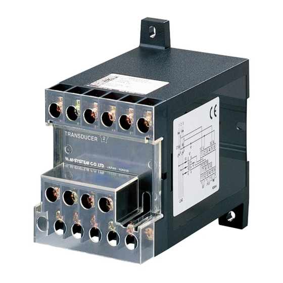
Power Transducer Series LT-UNIT
POWER FACTOR TRANSDUCER
Functions & Features
• Providing a DC output signal in proportion to power factor
• DC output containing little ripple is ideal for computer
input
• Isolation up to 2000 V AC
• High-density mounting
• Conforms to IEC 60688
• CE marking
Typical Applications
• Centralized monitoring and control of power management
system in a manufacturing facility or building
• Measuring power factor for a motor
72
(2.83)
143 (5.63)
mm (inch)
MODEL: LTPF–[1][2][3][4][5]–[6][7]
ORDERING INFORMATION
• Code number: LTPF–[1][2][3][4][5]–[6][7]
Specify a code from below for each [1] through [7].
(e.g. LTPF-115PA-R/T)
• Special output range (For codes Z & 0)
[1] CONFIGURATION
1: 3-phase / 3-wire
4: 3-phase / 4-wire
[2] VT INPUT (balanced load)
For 3-phase / 4-wire, phase voltages (e.g. 110 V / √3 ) are used.
1: 100, 110, 115, 120 V AC
2: 190, 200, 210, 220, 230, 240 V AC
4: 380, 400, 415, 430, 440, 480 V AC
SEN TRONIC
AG
Produkte, Support und Service
111
(4.3 7)
Rugghölzli 2
CH - 5453 Busslingen
[3] CT INPUT (balanced load)
1: 1 A AC
2: 2 A AC
5: 5 A AC
[4] OUTPUT SIGNAL POLARITY
P: Negative in lag, positive in lead
M: Negative in lead, positive in lag
[5] OUTPUT
Current
A: 4 – 20 mA DC (Load resistance 500 Ω max.)
FW: -10 – +10 mA DC (Load resistance 1000 Ω max.)
GW: -1 – +1 mA DC (Load resistance 10 kΩ max.)
JW: -5 – +5 mA DC (Load resistance 2000 Ω max.)
Z: Specify current (See OUTPUT SPECIFICATIONS)
Voltage
6: 1 – 5 V DC (Load resistance 5000 Ω min.)
1W: -10 – +10 mV DC (Load resistance 10 kΩ min.)
2W: -100 – +100 mV DC (Load resistance 100 kΩ min.)
3W: -1 – +1 V DC (Load resistance 1000 Ω min.)
4W: -10 – +10 V DC (Load resistance 10 kΩ min.)
5W: -5 – +5 V DC (Load resistance 5000 Ω min.)
0: Specify voltage (See OUTPUT SPECIFICATIONS)
[6] AUXILIARY POWER SUPPLY
AC Power
K3: 100 – 120V AC
(Operational voltage range 85 - 132 V AC, 47 - 66 Hz)
L3: 200 – 240V AC
(Operational voltage range 170 - 264 V AC, 47 - 66 Hz)
DC Power
R: 24 V DC
(Operational voltage range 24 V ±10 %, ripple 10 %p-p max.)
V: 48 V DC
(Operational voltage range 48 V ± 10 % , ripple 10 % p-p max.)
P: 110 V DC
(Operational voltage range 85 – 150 V, ripple 10 %p-p max.)
(CE not available)
[7] OPTIONS
Terminal cover
blank: Without
/T: With
GENERAL SPECIFICATIONS
Connection: M4 screw terminals (torque 1.2 N·m)
Screw terminal: Chrome-plated steel
Housing material: Flame-resistant resin (black)
Isolation: Voltage input to current input to output to power
Tel. +41 (0)56 222 38 18
Fax +41 (0)56 222 10 12
MODEL: LTPF
mailbox@sentronic.com
www.sentronic.com
Advertisement
Table of Contents

Related Manuals for M-system LT-UNIT Series


Summary of Contents for M-system LT-UNIT Series
- Page 1 MODEL: LTPF Power Transducer Series LT-UNIT [3] CT INPUT (balanced load) 1: 1 A AC 2: 2 A AC POWER FACTOR TRANSDUCER 5: 5 A AC Functions & Features • Providing a DC output signal in proportion to power factor [4] OUTPUT SIGNAL POLARITY •...
- Page 2 Mounting: Surface or DIN rail Note: A device which employs different measuring methods Weight: 450 g (0.99 lbs) may show different outputs from that of M-System’s with distorted input waveforms. Frequency: 50 or 60 Hz PERFORMANCE in percentage of span ■...
- Page 3 MODEL: LTPF CONNECTION DIAGRAM 3-PHASE/3-WIRE 3-PHASE/4-WIRE SOURCE SOURCE FUSE FUSE OUTPUT OUTPUT – – U(+) U(+) POWER POWER V(–) V(–) LOAD LOAD *The transducer can be powered from the input voltage when the voltage is sufficiently stable and meets within the range of auxiliary power supply of the unit specified in the data sheet/instruction manual.
- Page 4 BEFORE USE ..• Do not install cables (power supply, input and output) close to noise sources (relay drive cable, high frequency Thank you for choosing M-System. Before use, please check line, etc.). contents of the package you received as outlined below.
- Page 5 LTPF TERMINAL CONNECTIONS Connect the unit as in the diagram below or refer to the connection diagram on the side of the unit. ■ 3-PHASE/3-WIRE ■ 3-PHASE/4-WIRE SOURCE SOURCE FUSE FUSE OUTPUT OUTPUT – – U(+) U(+) POWER POWER V(–) V(–) LOAD LOAD...
- Page 6 LTPF EXTERNAL DIMENSIONS unit: mm (inch) 10 (.39) 16–M4 SCREW 2–M4 MTG HOLE TERMINAL COVER (option /T) DIN RAIL 35mm wide 11 12 13 14 15 16 8 (.31) 54 (2.13) (.12) 143 (5.63) [4 (.16)] 72 (2.83) • When mounting, no extra space is needed between units. SEN TRONIC Rugghölzli 2 Tel.
Need help?
Do you have a question about the LT-UNIT Series and is the answer not in the manual?
Questions and answers