Advertisement
Power Transducer Series LT-UNIT
FREQUENCY TRANSDUCER
Functions & Features
• Provides a DC output signal in proportion to the deviation
(±5 Hz) from the center frequency (50 Hz or 60 Hz)
• DC output containing little ripple is ideal for computer
input
• Isolation up to 2000 V AC
• High-density mounting
• Conforms to IEC 60688
• CE marking
Typical Applications
• Centralized monitoring and control of power management
system in manufacturing facility or building
• Measuring frequency for UPS
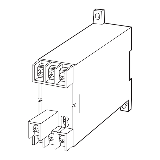
39
(1.54)
111
(4.3 7)
143 (5.63)
mm (inch)
MODEL: LTHZ–[1][2][3]–[4][5]
ORDERING INFORMATION
• Code number: LTHZ–[1][2][3]-[4][5]
Specify a code from below for each [1] through [5].
(e.g. LTHZ-11A-R/T)
• Special output range (For codes Z & 0)
[1] FREQUENCY
1: 45 – 55 Hz
2: 55 – 65 Hz
3: 45 – 65 Hz
[2] VT INPUT
1: 100, 110, 115, 120 V AC
2: 190, 200, 210, 220, 230, 240 V AC
4: 380, 400, 415, 430, 440, 480 V AC
SEN TRONIC
AG
Produkte, Support und Service
[3] OUTPUT
Current
A: 4 – 20 mA DC (Load resistance 500 Ω max.)
D: 0 – 20 mA DC(Load resistance 500 Ω max.)
F: 0 – 10 mA DC (Load resistance 1000 Ω max.)
G: 0 – 1 mA DC (Load resistance 10 kΩ max.)
J: 0 – 5 mA DC (Load resistance 2000 Ω max.)
Z: Specify current (See OUTPUT SPECIFICATIONS)
Voltage
1: 0 – 10 mV DC (Load resistance 10 kΩ min.)
2: 0 – 100 mV DC (Load resistance 100 kΩ min.)
3: 0 – 1 V DC (Load resistance 1000 Ω min.)
4: 0 – 10 V DC (Load resistance 10 kΩ min.)
5: 0 – 5 V DC (Load resistance 5000 Ω min.)
6: 1 – 5 V DC (Load resistance 5000 Ω min.)
0: Specify voltage (See OUTPUT SPECIFICATIONS)
[4] AUXILIARY POWER SUPPLY
AC Power
K3: 100 – 120V AC
(Operational voltage range 85 - 132 V AC, 47 - 66 Hz)
L3: 200 – 240V AC
(Operational voltage range 170 - 264 V AC, 47 - 66 Hz)
DC Power
R: 24 V DC
(Operational voltage range 24 V ±10 %, ripple 10 %p-p max.)
V: 48 V DC
(Operational voltage range 48 V ± 10 % , ripple 10 % p-p max.)
P: 110 V DC
(Operational voltage range 85 – 150 V, ripple 10 %p-p max.)
(CE not available)
[5] OPTIONS
Terminal cover
blank: Without
/T: With
GENERAL SPECIFICATIONS
Connection: M4 screw terminals (torque 1.2 N·m)
Screw terminal: Chrome-plated steel
Housing material: Flame-resistant resin (black)
Isolation: Input to output to power
Computation: One-shot
Overrange output: Approx. -10 to +120 % at 1 – 5 V
Zero adjustment: -5 to +5 % (front)
Span adjustment: 95 to 105 % (front)
INPUT SPECIFICATIONS
Input burden: 1 VA
Overload capacity: 150 % of rating for 10 sec., 120 %
Rugghölzli 2
Tel. +41 (0)56 222 38 18
CH - 5453 Busslingen
Fax +41 (0)56 222 10 12
MODEL: LTHZ
mailbox@sentronic.com
www.sentronic.com
Advertisement
Table of Contents

Related Manuals for M-system LT-UNIT Series


Summary of Contents for M-system LT-UNIT Series
- Page 1 MODEL: LTHZ Power Transducer Series LT-UNIT [3] OUTPUT Current A: 4 – 20 mA DC (Load resistance 500 Ω max.) FREQUENCY TRANSDUCER D: 0 – 20 mA DC(Load resistance 500 Ω max.) Functions & Features F: 0 – 10 mA DC (Load resistance 1000 Ω max.) •...
-
Page 2: Output Specifications
MODEL: LTHZ continuous EN 61010-1 Operational range: 85 – 120 % of rating Measurement Category II (input, output) Installation Category II (power) Pollution Degree 2 OUTPUT SPECIFICATIONS Input to output or power: Reinforced insulation (550 V) • DC Current: 0 – 20 mA DC Output to power: Reinforced insulation (300 V) Minimum span: 1 mA IEC Standard: IEC 60688... -
Page 3: Connection Diagram
MODEL: LTHZ CONNECTION DIAGRAM SOURCE FUSE OUTPUT – U(+) LOAD POWER V(–) *The transducer can be powered from the input voltage when the voltage is sufficiently stable and meets within the range of auxiliary power supply of the unit specified in the data sheet/instruction manual. - Page 4 BEFORE USE ..• Do not install cables (power supply, input and output) close to noise sources (relay drive cable, high frequency Thank you for choosing M-System. Before use, please check line, etc.). contents of the package you received as outlined below.
- Page 5 LTHZ TERMINAL CONNECTIONS ADJUSTMENT PROCEDURE Connect the unit as in the diagram below or refer to the con- This unit is calibrated at the factory to meet the ordered nection diagram on the side of the unit. specifications, therefore you usually do not need any cali- bration.
Need help?
Do you have a question about the LT-UNIT Series and is the answer not in the manual?
Questions and answers