Advertisement
This is a safety alert symbol and should never be ignored. When you see this symbol on labels or in manuals, be alert to
the potential for personal injury or death.
Improper installation, adjustment, alteration, service
or maintenance can cause property damage, personal
injury or loss of life. Installation and service must be
performed by a licensed professional installer (or
equivalent), service agency or the gas supplier.
Installation and servicing of air conditioning equipment
can be hazardous due to internal refrigerant pressure
and live electrical components. Only trained and
qualified service personnel should install or service
this equipment. Installation and service performed by
unqualified persons can result in property damage,
personal injury or death.
For your safety, do not store or use gasoline or other
flammable vapors and liquids in the vicinity of this or any
other appliance. Such actions could result in property
damage, personal injury, or death.
Manufactured By
Allied Air Enterprises LLC
A Lennox International, Inc. Company
215 Metropolitan Drive
West Columbia, SC 29170
Check that equipment complies with all applicable building codes, laws, and regulations for its intended use prior to installation.
507390-02
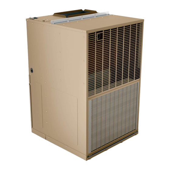
INSTALLATION INSTRUCTIONS
EWC V-Series
This manual must be left with the homeowner for future reference.
WARNING
WARNING
WARNING
Models
TM
Table of Contents
Unit Dimensions ..........................................................2
Installation ...................................................................3
Electrical Connections .................................................4
Operation .....................................................................5
Maintenance ................................................................6
Wiring Diagrams ..........................................................8
Installation shall be made in accordance with the
requirements of the local utility and other authorities
having jurisdiction, or with the National Fuel Gas
Code, ANSI Z223.1 (latest edition) and the National
Electrical Code. Any alteration of internal wiring will void
certification and warranties.
These units are not approved for mobile home
applications. Such use could result in property damage,
personal injury, or death.
*P507390-02*
Issue 2127
CAUTION
WARNING
(P) 507390-02
Page 1 of 12
Advertisement

Related Manuals for Magic-Pak All-In-One EWC V Series


Summary of Contents for Magic-Pak All-In-One EWC V Series
-
Page 1: Table Of Contents
INSTALLATION INSTRUCTIONS EWC V-Series Models This manual must be left with the homeowner for future reference. This is a safety alert symbol and should never be ignored. When you see this symbol on labels or in manuals, be alert to the potential for personal injury or death. -
Page 2: Unit Dimensions
Unit Dimensions Line Voltage Connections Thermostat Wiring Connections 1-3/4 Supply 1-1/2 2 3/4 13-3/8 Supply Supply 18-1/4 43-3/16 Return 2-7/8 29-7/16 27-7/8 Page 2 of 12 Issue 2127 507390-02... -
Page 3: Installation
Installation Location Installation shall be made in accordance with local utility requirements and any other authorities having jurisdiction. The unit is approved for indoor installation only. It must not be installed completely outside. Duct connections as well as service access must be inside the building. The interior General portions of the unit may be surrounded by a closet with The MagicPak All-In-One™... -
Page 4: Electrical Connections
Installing with a Wall Sleeve Condensate Drain Refer to the installation instructions packed with the wall To install the condensate line, connect one end of the sleeve and Figure 1 for guidance in assembly and mounting plastic tube over the 5/8” O.D. fitting in the center of the using a wall sleeve. -
Page 5: Operation
Ductwork permanent filter, shake the filter to remove excess dirt and/or use a vacuum cleaner. Wash the filter in soap or Provide ductwork sufficiently large to handle the larger detergent water and re-install after filter is dry. of the air volumes for heating or cooling provided by this model. -
Page 6: Maintenance
Maintenance Cooling Chassis Remove the screws from the panel directly in front of the blower and remove the panel. Also remove the The refrigeration system contained in the cooling chassis additional screws located near the top edge of the normally requires no maintenance since it is a closed self- control panel. - Page 7 Indoor Blower Unit Voltage Model Speed " w.c. " w.c. " w.c. " w.c. " w.c. TAP 1 (HEAT) * 208 or 230 TAP 2 (HEAT) 208 or 230 EWC0512P12B TAP 3 (HEAT) 208 or 230 TAP 4 (COOL) † 208 or 230 TAP 5 (COOL) 208 or 230...
-
Page 8: Wiring Diagrams
Wiring Diagrams Figure 3. Wiring Diagram - EWC*12P12B, EWC*12P18B Page 8 of 12 Issue 2127 507390-02... - Page 9 LINE VOLTAGE-FACTORY COOLING HEATING LINE VOLTAGE-FIELD MODEL SPEED SPEED LOW VOLTAGE-FACTORY EWC1012P24B TAP #4 TAP #3 LOW VOLTAGE-FIELD CIRCUITS ENERGIZED 208/230V-1 -60Hz POWER SUPPLY NOTE: OPERATING MODE CIRCUIT THERMOSTAT COPPER CONDUCTORS HEATING IF ANY OF THE ORIGINAL WIRES ARE ONLY. COOLING R-G-Y REPLACED THE SAME SIZE AND TYPE...
- Page 10 CIRCUITS ENERGIZED COOLING HEATING LINE VOLTAGE-FACTORY MODEL SPEED SPEED OPERATING MODE CIRCUIT LINE VOLTAGE-FIELD HEATING LOW VOLTAGE-FACTORY EWC1512P24B TAP #4 TAP #3 COOLING R-G-Y LOW VOLTAGE-FIELD NOTE: 208/230V-1 -60Hz IF ANY OF THE ORIGINAL WIRES ARE POWER SUPPLY THERMOSTAT COPPER CONDUCTORS REPLACED THE SAME SIZE AND TYPE ONLY.
- Page 11 Figure 6. Wiring Diagram - EWC1012P30B 507390-02 Issue 2127 Page 11 of 12...
- Page 12 Figure 7. Wiring Diagram - EWC1512P30B Page 12 of 12 Issue 2127 507390-02...
Need help?
Do you have a question about the All-In-One EWC V Series and is the answer not in the manual?
Questions and answers