Advertisement
Quick Links
This is a safety alert symbol and should never be ignored. When you see this symbol on labels or in
manuals, be alert to the potential for personal injury or death.
Improper installation, adjustment, alteration, service
or maintenance can cause property damage, personal
injury or loss of life. Installation and service must be
performed by a licensed professional installer (or
equivalent), service agency or the gas supplier.
Do not store combustible materials near the furnace or
warm air ducts. The material may ignite by spontaneous
combustion creating a fire hazard.
These units are not approved for mobile home
applications. Such use could result in property damage,
personal injury, or death.
If these instructions are not followed exactly, a fire
or explosion may result causing property damage,
personal injury, or loss of life.
Manufactured By
Allied Air Enterprises LLC
A Lennox International, Inc. Company
215 Metropolitan Drive
West Columbia, SC 29170
507388-01
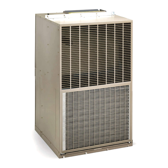
INSTALLATION INSTRUCTIONS
HWC8 V-Series
This manual must be left with the homeowner for future reference.
WARNING
WARNING
WARNING
CAUTION
Save these instructions for future reference
Models
TM
Table of Contents
Installation ...................................................................2
Electrical Connections .................................................6
Start-Up .....................................................................10
Operation ...................................................................10
Maintenance ..............................................................11
Wiring Diagrams ........................................................15
For your safety, do not store or use gasoline or other
flammable vapors and liquids in the vicinity of this or any
other appliance. Such actions could result in property
damage, personal injury, or death.
Installation shall be made in accordance with the
requirements of the local utility and other authorities
having jurisdiction, or with the National Fuel Gas
Code, ANSI Z223.1 (latest edition) and the National
Electrical Code. Any alteration of internal wiring will void
certification and warranties.
*P507388-01*
Issue 1732
WARNING
CAUTION
(P) 507388-01
Page 1 of 16
Advertisement

Related Manuals for Magic-Pak HWC8 V Series


Summary of Contents for Magic-Pak HWC8 V Series
-
Page 1: Table Of Contents
INSTALLATION INSTRUCTIONS HWC8 V-Series Models This manual must be left with the homeowner for future reference. This is a safety alert symbol and should never be ignored. When you see this symbol on labels or in manuals, be alert to the potential for personal injury or death. Table of Contents WARNING Installation ..............2... -
Page 2: Installation
Location The design is certified for indoor installation only. The WARNING interior portions of the unit may be surrounded by a closet with minimum clearances to combustible material held Install operate and maintain unit in accordance with to 0” sides, 2” top, and 1” front and plenum. Adequate manufacturer’s instructions. - Page 3 • A room thermostat must control the furnace. The use Seal the space between the wall sleeve and the building of fixed jumpers that will provide continuous heating is opening with non-hardening caulking compound. The seal not allowed. must be weather-tight to prevent entrance of moisture and water into the building.
- Page 4 Combustion Air Seal the space between the unit and building opening using a non-hardening caulking compound. The seal This unit is a direct - vent furnace which obtains all air must be weather-tight to prevent entrance of moisture needed for combustion from outdoors. and water into the building.
- Page 5 Removal of Unit from Common Venting System Units for operation with propane must be converted with a kit supplied by the manufacturer and require for operation When an existing furnace is removed from a common an inlet pressure of 11” W.C. minimum and 13” W.C. venting system serving other appliances, the venting maximum.
-
Page 6: Electrical Connections
Provide a drip leg in the supply piping located exterior to the unit. Piping connections must be sealed with non- CAUTION hardening pipe joint compound resistant to propane. Electrostatic discharge can affect electronic components. Take precautions during furnace installation and service to protect the furnace’s electronic controls. - Page 7 to extend into the bottom of the box. Pull the leads through the knock-out and into the box. Remove a knock-out for the main power supply leads. Secure the junction box to the top panel using screws. Connect the unit wiring leads to the main power supply or the switch as desired.
- Page 8 Supply and Return Duct(s) Adjustments – Cooling Section (HWC models) Provide duct(s) sized sufficiently to handle the larger of the No adjustments are required or should be attempted air volumes for heating or cooling provided by this model. regarding any of the components of the cooling chassis. The chassis should be checked to see that none of the Connect the supply duct to the top of the unit using canvas wiring is loose or missing.
- Page 9 Airflows and Heating Temperature Rises as a Function of External Static Pressure 0.1“ w.c. 0.2“ w.c. 0.3“ w.c. 0.4“ w.c. Rise Indoor Unit Temp Temp Temp Temp Model Range Rise Blower Voltage SCFM Rise SCFM Rise SCFM Rise SCFM Rise (°F) (°F) Speed...
-
Page 10: Start-Up
Start-Up Operation For Your Safety Read Before Lighting Operation of the unit is automatic and will provide heating and cooling depending on the setting of the thermostat. WARNING Heating Turn on main power supply. If you do not follow these instructions exactly, a fire Open manual gas shutoff valve. -
Page 11: Maintenance
Continuous Fan Operation Continuous operation of the air handling blower will be WARNING obtained if the thermostat fan switch is set to “ON”. With the thermostat fan switch set to “AUTO”, the air handling ELECTRICAL SHOCK, FIRE OR EXPLOSION blower will cycle corresponding with the thermostat cycling. HAZARD Failure to follow safety warnings exactly could result in To Shut Down Unit... - Page 12 Burner & Manifold Assembly First, carefully pull the burner assembly toward you until it is clear of the locating pins in the mounting To remove the burner & manifold assembly: brackets. 1. Disconnect electrical service and turn off gas to the Then move the assembly away from the vest panel.
- Page 13 Lift the bracket clear of the screws and carefully lower 1. Remove the control board mounting bracket as the bracket and ignition board to the bottom of the described previously. compartment. Disconnect the two orange and yellow wires at the It may be necessary to remove the inducer prover primary limit switch.
- Page 14 Heat Exchanger Cooling Chassis The heat exchanger should be inspected periodically and The refrigeration system contained in the cooling chassis cleaned if necessary. When cleaning use a stiff brush with normally requires no maintenance since it is a closed, a wire handle to remove scale and soot. To access the self-contained system.
-
Page 15: Wiring Diagrams
Wiring Diagrams Figure 10. 507388-01 Issue 1732 Page 15 of 16... - Page 16 Figure 11. Page 16 of 16 Issue 1732 507388-01...
Need help?
Do you have a question about the HWC8 V Series and is the answer not in the manual?
Questions and answers
I **** looking for a combustion inducer for HWC8R6009P24A2A model
The combustion inducer in the Magic-Pak HWC8R6009P24A2A model draws the combustion products out of the heat exchanger along with dilution air and forces the mixture from the unit to the outside. It is an integral part of the venting system, which must not be modified or extended.
This answer is automatically generated