
Related Manuals for Fourgroup Full-App 2


Summary of Contents for Fourgroup Full-App 2
- Page 1 Date : 27/07/15 Rev. 02 Sw. 9.8 PR .T : FG006234 USE AND INSTALLATION HANDBOOK s.r.l. - FOURGROUP Via Enrico Fermi, 8 - 35020 Polverara (PD) - ITALY Tel. +39.049.9772407 - Fax. +39.049.9772289 - www.fourgroup.it - info@fourgroup.it...
-
Page 2: Table Of Contents
INDEX OF TOPICS Warnings pag. 3 Overview Handling General description Installation Light indications and buttons Displays General operation Parameter setting 10. General settings 11. Settings pumps 12. Operating programs 13. Gsm modem setting 14. Alarm setting 15. Electric connections 16. Application examples 17. -
Page 3: Warnings Pag
The purpose of this manual is to provide the necessary information for the proper installation, use and maintenance of FULL-APP 2. The user should read this manual before operating the unit. Improper use may cause damage to the machine and lead to the forfeiture of the warranty coverage. Always specify the model identification code and the construction number when requesting technical information or spare parts from our Sales and Service department. -
Page 4: Handling
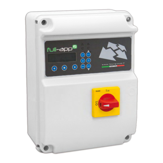
FULL-APP² is an electronic panel for direct start-up of 2 single or three phase pumps with dry running protection via cos- φ and minimum current, remote management with gsm and app. FOURGROUP S.r.l. shall not be liable for any damage caused or suffered by the unit as a result of its unauthorised or improper use. -
Page 5: Installation
5. INSTALLATION Fix the control panel for a stable support with screws and screw anchor using the holes arranged in the box (fig. 1) or the fixing bracket if present. To fix the cables in their terminals use a tool of the proper size to avoid the damaging of the screws or of their seat. If use an electric screwier pay attention not to spoil the thread or the screws. -
Page 6: Light Indications And Buttons
6. LIGHT INDICATIONS AND BUTTONS DISPLAY backlit blue to display the parameters of the system AUT button to activate the automatic mode of operation; when the green led is on it indicates the automatic functional mode is active START green led to indicate the pump is currently working. the flashing led indicates it’s waiting for the start timer to expire ALARM red led to indicate an alarm is active;... -
Page 7: Displays
The main default display shows the current working parameters. By pressing the button is possible to move to different screens and show the working parameter of the pumps (one screen for every pump; therefore, for the full-app 2, there will be 2 screens to display the parameters of each pump):... - Page 8 IMPOSTAZIONI GENERAL IMPOSTAZIONI SETTINGS PROGRAMMI OPERATING IMPOSTAZIONE GSM MODEM IMPOSTAZIONE ALARM PRESS ENTER TO ENTER PER GENER. QUADRO SETTINGS PARAM. POMPE PUMPS DI FUNZIONAM. PROGRAMS MODEM GSM SETTING ALLARMI SETTING USCIRE DA SETUP SET-UP EXIT (PG. 11) (PG. 11) (PG. 22) (PG.
- Page 9 CONFIGURATION CONFIGURATION CONFIGURATION RELAY 1 RELAY 2 GSM ALARM (PG. 37) (PG. 37) (PG. 38) CONFIGURATION MODE CONFIGURATION MODE CONFIGURATION MODE CONFIGURATION (PG. 37-36) (PG. 37-35) (PG. 37-36) (PG. 37-35) (PG. 37-36) (PG. 38) (PG. 38-36) PHONE CONNECT TEST CONNECT TEST CONNECT TEST NR.
-
Page 10: General Operation
8. GENERAL OPERATION To modify the parameter settings of operation the user will need to enter the programming mode, then you must pressing simultaneously the two buttons until the display shows the following password screen: Password 0000 To continue the correct password is required (the default password is 0000) and press the button To enter a new password you need to change the parameter "Password Setting"... -
Page 11: General Settings
10. GENERAL SETTINGS Once entered in the programming mode the first horizontal menu will be: Press Enter to General Settings pumps Set-up Exit settings Pressing navigate the horizontal menus. With the button displays the corresponding vertical parameter: General settings The parameter “Select Language” will set the language selection for the alarm messages to be displayed (the “X”... - Page 12 Pressing the button will gain access to the set of parameters related to the reading of the input of 4-20mA device: In the parameter “bar/mt” is possible to select the unit of measurement used in the display of Enable 4-20mA the signal 4-20 mA.
- Page 13 To manually set the “relative zero” press the button Learn Set-up Zero: XX.XX Zero: XX.XX The parameter “Set-up Zero” will set the value of the relative zero manually. The “X” indicates the digit of the parameter to modify. Set-up The range of value is from 00.00 to 99.99 (bar or meters depending on the choice made Zero: XX.XX previously).
- Page 14 The parameter “Stop Level P1” will set the level (in bar or meter units depending on the mode previously selected) for which to stop Pump 1. In the case of a pressurized system this alarm corresponds to the pressure parameter “Pressure stop P1”. This parameter is usable only in the DIGIT programming mode and in the MULTITANK Stop Level P1 programming mode (only for Pump 1).
- Page 15 In parameter "Filter reading" you can increase / decrease the delay of the reading of 4-20 mA signal: setting a low value reading signal will be faster, with a higher value will become slower. Increase this coefficient is particularly useful in cases in which the reading signal (pressure / Filter reading Level) of the sensor becomes unstable maybe because of rapid changes in pressure / Level.
- Page 16 The parameter “Stop Delay” will set a time delay on the stopping of the pumps after the stopping condition is met; for example, the opening of a stop flow switch /pressure switch (for operating modes Dark, Clean, Multitank). Therefore, once the trigger is set for the stopping condition the pumps will continue to work for the amount of time set in this parameter.
- Page 17 The parameter “Delay Alarm Voltage” will set a delay time on the activation of the voltage’s alarm (if previously enabled); the trigger condition (over/under voltage) must persist for the length of time set in this parameter in order to trigger the alarm. For example, if the Delay Alarm is set to 10 seconds and the trigger condition persists Delay alarm voltage...
- Page 18 The parameter “Self-test pumps” will set the timer based value to be used by the Control Panel full-app to execute all the pumps Functional Periodic Self-test (the periodic self-test is to avoid the possibility the pumps might be blocked after being idle for a long period due to the Self-Test pumps conditions of the system).
- Page 19 To move to the next horizontal parameter press the button Turn-Off MANUAL Simultaneity Rotating pumps 0=NO 1=R 2=A X 0=ON XXXsec Max pumps nr.X The parameter “Simultaneity Max pumps” will set the number of pumps can be used simultaneously. For example, setting the value to “1” it will have a maximum of 1 pump even if Simultaneity the conditions for both pumps are active.
- Page 20 The parameter “Change pump every XXX hours” is related to the type of timer rotation that is enabled via the previous parameter. It is possible to set the timer to how many hours it will Change Pump swap the starting priority: pump 1/pump 2; pump 2/pump 1. every XXX hours The “X”...
- Page 21 Restart Setting Restart Setting Exclude Restart Restart3 XXX min Restart4 XXX min 0=NO 1=YES ->X The parameter “Restart Setting, Restart 4”, as previous 3 parameters, is related to the dry running alarm. It is possible to set the timer delay for the automatic restart after the 4th dry running alarm .
-
Page 22: Settings Pumps
The parameter “Setting Password” allows the user to set/modify the password to access the programming menu. Setting The “X” indicates the setting of the parameter to modify. Password XXXX It’s possible to a set a password of 4 digits. Factory default password is “0000”. To return to the first horizontal parameter press the button Setting Sel.Language: X... - Page 23 The parameter “P1 Alarm Delay I max” will set the time delay for the activation of the alarm for maximum current consumption (overcurrent): the threshold must be crossed (overcurrent) Configuration for the amount of time specified for the alarm to trigger and to stop the pump. Pump1 For example, if the alarm time delay is set to 10 seconds then the threshold is crossed continuously for 10 seconds for the alarm to activate;...
- Page 24 To set the maximum time of continuous operation of the pump is necessary to pass to the parameter "Max Continuous working" by pressing The parameter “Max Continuous working” will set maximum time of continuous working operation of the pump. If the pump works continuously for a period of time longer than the set Enable Max Cont.
- Page 25 To move to the next horizontal parameter press the button Enable Max Start Enable Max Start Enable Max Int. Minute 0=NO X Hour 0=NO X Klixon 0=NO X The parameter “Enable Max Start Hour” will enable/disable the alarm for the maximum number of starts per hour of the pump.
- Page 26 Press the button to move to the menu for setting the maximum number of interventions Klixon (“Max Intervention Klixon P1”): The parameter “Max interventions Klixon P1” will set the max number of Klixon events that the pump can handle. If the number of Klixon events is higher than the set value the pump will be Enable Max Int.
- Page 27 Press the button to update the time remaining for the next service with the pump’s duration of work already executed (the value will be displayed on the parameters “h XXX”). At this point the next service request will happen after “time set on the parameter P1 service request”...
- Page 28 Max Current Min Current Cosø Min Pump 1 XX.XA Pump 1 XX.XA Pump 1 X.XX The parameter “Min Current Pump 1” will set the minimum value of current consumption allowed (undercurrent). Below the set value (for the duration specified in the parameter “P1 Delay Alarm Imin”) the pump will stop and will display an alarm (Minimum current) and it will be possible to activate one or more alarm output (based on the settings in the menu “Alarms Min Current...
-
Page 29: Operating Programs
At this point the horizontal menu “Settings Pumps” has been fully programmed and you can proceed to the next menu. To go back to the horizontal menu “Settings Pumps” press the button General Settings Operating Settings Pumps Programs Press again the button to move to the next horizontal menu “Operating Programs”: 12. - Page 30 Inside the menu “Program DIGIT” is possible to activate/deactivate the operating mode “DIGIT” for the pumps (this operating mode will apply to all the pumps connected). The program DIGIT Program allows the starting and stopping of the pumps based on a signal coming from 4-20 mA device DIGIT (for example, level piezoresistive sensor, electronic pressure transducer,…).
- Page 31 To move to the next horizontal parameter press the button Operating mode Enable Empty/Fill CLEAN The parameter “Enable CLEAN” will enable/disable the program operating mode Clean. Once enabled the mode CLEAN it will apply to all the installed pumps. Enable To enable the operating mode Clean press the button to save its setting.
- Page 32 With the parameter “Operation Mode Pump 1” it is possible to select one of the following modes for pump 1: Program 1=Operating mode CLEAN – EMPTY MULTITANK 2=Operating mode CLEAN – FILL 3=Operating mode DARK – EMPTY 4=Operating mode DARK – FILL Operation Mode 5=Operating mode DIGIT –...
-
Page 33: Gsm Modem Setting
13. GSM MODEM SETTING GSM Modem Alarms Programmi di Funzionamento Setting Setting Press the button to visualize the underneath vertical parameter: GSM Modem Setting With the vertical parameter “Station Name” is possible to give a name the control panel/system. The name will show in the SMS reply every time there will be a GSM connection test (see following parameters). - Page 34 The parameter “Phone nr.2” will set the second (3 in total) phone number to send the SMS messages for the status and alarms as well as the phone number allowed to remotely control Phone nr.2 the various parameter settings. The number needs to be entered with international prefix (for +XXXXXXXXXX example, +44…..) without any spaces.
-
Page 35: Alarm Setting
At this point the horizontal menu “GSM Modem Setting” has been fully programmed and it’s possible to proceed to the next menu. To go back to the horizontal menu press the button , we are back to horizontal menu “GSM Modem Setting”: Operating GSM Modem Alarms... - Page 36 To move to the next horizontal parameter press the button Configuration Mode 0=NO 1=SI 2=P X XXXXXXXXXXXXXXX The parameter “Configuration” sound alarm output is possible to set which alarms will activate Configuration the output (with mode described in the previous parameter). XXXXXXXXXXXXXXX The “X”...
- Page 37 To go back to the horizontal menu press the button . Back to the horizontal menu “Configuration Sound Alarm”: Configuration Configuration Configuration GSM Alarm Sound Alarm Visual Alarm Press the button to move to the configuration of the next alarm output : Configuration Configuration Configuration...
- Page 38 The vertical parameter “Configuration Relay 2” will set the operating mode of the Q1 alarm output on the control panel. It is an output relay with changeover contact (voltage free) with screw terminals connectors (see page 40) (electric contacts characteristics: 250Vac, 5A in AC1).
-
Page 39: Electric Connections
15. ELECTRIC CONNECTIONS Connection of the control signals and protection on the main board SOUND ALARM OUTPUT (12V-30mA) DEVICE 4-20mA INPUT RELAY 1 ALARM OUTPUT (dry contacts) RELAY 2 ALARM OUTPUT (dry contacts) COMMANDS AND PROTECTION PUMPS INPUTS (the connections change depending on the operating mode;... - Page 40 Connection of the alarm and protection signals on the GSM board Quad-Band GSM 850/900 / 1800/1900 MHz - which operates in 2G (optional board) NOT USED INPUT SUPPLY BOARD (230-400Vac) VISUAL ALARM OUTPUT (12V-30mA) LED 1 red: - FIXED ON: gsm not configured - FLASHING: alarm active - OFF: OK! (GSM configured and no active alarm)
- Page 41 Connection of the power supply and single-phase pumps with internal capacitor (embedded) differential magnetotermic switch (not included) POWER 12V BATTERY PUMP 1 PUMP 2 SUPPLY INPUT GSM INPUT OUTPUT OUTPUT 1~230V (if present) 1~230V 1~230V...
- Page 42 Connection of the power supply and single-phase pumps with external capacitor C1: STARTING CAP. PUMP 1 C2: STARTING CAP. PUMP 2 differential magnetotermic switch (not included) POWER 12V BATTERY PUMP 1 PUMP 2 SUPPLY INPUT GSM INPUT OUTPUT OUTPUT 1~230V (if present) 1~230V 1~230V...
- Page 43 Connection of the power supply and trhee-phase pumps differential magnetotermic switch (not included) PUMP 1 PUMP 2 POWER 12V BATTERY OUTPUT OUTPUT SUPPLY INPUT GSM INPUT 3~400V (if present) 3~400V 3~400V...
-
Page 44: Application Examples
16. APPLICATION EXAMPLES DARK [empty] Connect only in the presence of water in the oil chamber probes DARK [fill] Connect only in the presence of water in the oil chamber probes... - Page 45 CLEAN [empty] Connect only in the presence of water in the oil chamber probes CLEAN [empty] Connect only in the presence of water in the oil chamber probes...
- Page 46 CLEAN [empty] CLEAN [empty]...
- Page 47 CLEAN [fill] Connect only in the presence of water in the oil chamber probes DIGIT [empty] Connect only in the presence of water in the oil chamber probes 4÷20 m A...
- Page 48 DIGIT [empty] Connect only in the presence of water in the oil chamber probes 4÷20 m A DIGIT [fill] 4÷20 m A...
- Page 49 MULTITANK POMPA 1 - CLEAN [empty] POMPA 2 - CLEAN [empty] Connect only in the presence of water in the oil chamber probes MULTITANK POMPA 1 - CLEAN [empty] POMPA 2 - DARK [empty] Connect only in the presence of water in the oil chamber probes...
- Page 50 MULTITANK POMPA 1 - DARK [empty] POMPA 2 - DARK [empty] Collegare solo in presenza delle sonde acqua in camera olio MULTITANK POMPA 1 - DIGIT [empty] POMPA 2 - CLEAN [empty] 4÷20 m A...
-
Page 51: Stop Of The Pumps
17. STOP OF THE PUMPS Motor stop may occur in the following ways: - In "manual" by releasing the MANUAL button (after the time set in parameter "Turn-Off MANUAL "); - In "automatic" mode when there is no consensus from the control inputs or by pressing "0" button; - In "automatic"... -
Page 52: Conformity Declaration
Polverara – Italy, 12/02/2015 Technical Manager (Grigoletto Per. Ind. Walter) FOURGROUP s.r.l. - Via Enrico Fermi, 8 - 35020 Polverara (PD) - ITALY - Tel. +39.049.9772407 - Fax. +39.049.9772289 - www.fourgroup.it - info@fourgroup.it... -
Page 53: General Conditions Of Sale
Fourgroup S.r.l. or its suppliers; c) failure on the part of the Buyer to provide Fourgroup S.r.l., in good time, with any information it has undertaken to provide and necessary for the supply and/or materials to be delivered. - Page 54 13. Proprietorship of goods. Indemnity 13.1. The property of the goods forming the subject of this sale is of Fourgroup S.r.l. and shall be transferred to the Buyer only upon full payment of the agreed price by the Buyer pursuant to articles 1523 f. of the Italian Civil Code.
Need help?
Do you have a question about the Full-App 2 and is the answer not in the manual?
Questions and answers