Table of Contents
Advertisement
Advertisement
Table of Contents

Related Manuals for Fourgroup Xtreme Series


Summary of Contents for Fourgroup Xtreme Series
- Page 1 Data : 03/04/17 Rev. 01 Sw. 1.A PR .T : FG016122 USE AND INSTALLATION HANDBOOK...
-
Page 2: Table Of Contents
INDEX OF TOPICS Warnings pag. 3 Overview Handling General description Installation Light indications and buttons Displays General operation Parameter setting 10. General settings 11. Settings pump 12. Operating programs 13. Gsm modem setting 14. Alarm setting 15. Restore settings 16. Alarm list 17. -
Page 3: Warnings Pag
1. WARNINGS The following symbols, accompanied by the words: “DANGER”, “WARNING”, indicate the potential hazard resulting from failure to observe the associated warning, as specified below: Failure to observe this warning may result in electric shock Failure to observe this warning may cause personal injury and/or damage to property Failure to observe this warning may cause damage to the pump, the unit or the system... -
Page 4: Handling
XTREME¹ is an electronic panel for direct start-up of 1 single or three phase pump with dry running protection via cosφ and minimum current, remote management with gsm and app. FOURGROUP S.r.l. shall not be liable for any damage caused or suffered by the unit as a result of its unauthorised or improper use. -
Page 5: Installation
5. INSTALLATION Fix the control panel for a stable support with screws and screw anchor using the holes arranged in the box (fig. 1) or the fixing bracket if present. To fix the cables in their terminals use a tool of the proper size to avoid the damaging of the screws or of their seat. If use an electric screwier pay attention not to spoil the thread or the screws. -
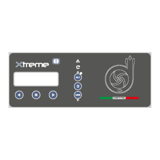
Page 6: Light Indications And Buttons
6. LIGHT INDICATIONS AND BUTTONS DISPLAY backlit blue to display the parameters of the system ALARM red led to indicate an alarm is active; when the red led is on it indicates the presence of an alarm and that made the pump stopped START green led to indicate the pump is currently working. -
Page 7: Displays
7. DISPLAYS The overall menu settings are composed of a series of horizontal menus that allows access to sets of horizontal and verticals parameters. As the following flowchart example: HORIZONTAL MENU’ VERTICAL PARAMETERS HORIZONTAL PARAMETERS NOTE: on the next page shows the complete flow chart programming When the panel is turned on the display will light up: SOFTWARE REVISION... - Page 8 GENERAL SETTINGS OPERATING GSM MODEM ALARM RESTORE PRESS ENTER TO SETTINGS PUMPS PROGRAMS SETTING SETTING SETTINGS SET‐UP EXIT (PG. 11) (PG. 21) (PG. 27) (PG. 31) (PG. 34) (PG. 37) (PG. 10) PRESS ENTER TO CONFIRM (PG. 37) CONFIGURATION CONFIGURATION SOUND ALARM VISUAL ALARM (PG. 34) (PG. 35) MODE CONFIGURATION MODE (PG. 34) (PG. 34) (PG. 35‐34) STATION ENABLE MODEM PHONE PHONE NAME ...
- Page 9 CONFIGURATION CONFIGURATION RELAY 1 GSM ALARM (PG. 36) (PG. 36) CONFIGURATION MODE CONFIGURATION MODE CONFIGURATION (PG. 35‐34) (PG. 36‐34) (PG. 36‐34) (PG. 36) (PG. 37‐34) PHONE CONNECT TEST CONNECT TEST CONNECT TEST NR. 3 SMS NR. 1 SMS NR. 2 SMS NR. 3 (PG. 32) (PG. 33) (PG. 33) (PG. 33) PROGRAM PAUSA/LAVORO (PG.30 ) ENABLE STARTING CYCLE PAUSE TIME WORK TIME ENABLE DIGIT PAUSE/WORK PUMP 1 PUMP 1 PAUSE/WORK ...
-
Page 10: General Operation
8. GENERAL OPERATION To modify the parameter settings of operation the user will need to enter the programming mode, then you must pressing simultaneously the two buttons until the display shows the following password screen: Password 0000 To continue the correct password is required (the default password is 0000) and press the button To enter a new password you need to change the parameter "Password Setting"... -
Page 11: General Settings
10. GENERAL SETTINGS Once entered in the programming mode the first horizontal menu will be: General Settings pump Press Enter to Set-up Exit settings Pressing navigate the horizontal menus. With the button displays the corresponding vertical parameter: General The parameter “Select Language” will set the language selection for the alarm messages to be settings displayed (the “X”... - Page 12 Pressing the button will gain access to the set of parameters related to the reading of the input of 4-20mA device: In the parameter “Measure Units” is possible to select the unit of measurement used in the Enable 4-20mA display of the signal 4-20 mA. 0=NO 1=YES X Depending on the sensor type used you can choose from: (The “X”...
- Page 13 Enable Max 4-20 Zero Calibration min. Lev-Press 0=NO 1=YES X Learn / Sets XX.XX The parameter “Zero Calibration Learn/Sets” is used to choose whether to have an auto setting or manual setting of the RELATIVE zero of the 4-20mA sensor being used. Therefore, it’s Zero Calibration possible to set the “zero”...
- Page 14 The parameter “Start P1” will set the level/pressure (in meter or bar depending on the mode previously selected for which to start the Pump 1. This parameter is usable only in the DIGIT and MULTITANK programming mode, in all other Start P1 programming modes this parameter is inhibited.
- Page 15 To move to the next horizontal parameter press the button Hi.Flt.Pumps ON Hi.Flt.Pumps ON Enable 4-20mA 0=NO 1=YES X 0=NO 1=YES 0=NO 1=YES X In parameter " Hi.Flt.Pumps ON " you can decide the functionality of the alarm float. The alarm float (or more generally a consensus alarm, that is a dry contact closure at which the alarm is activated) must be physically connected to the XTREME framework (see section "Electric connections").
- Page 16 With the parameter “Enable Alarm Voltage” it is possible to activate/deactivate the alarm relative to the Mains Power Voltage of the control panel XTREME (Vmax e Vmin). This alarm will: - Stop all pumps from working Enable Alarm - Display the alarm Voltage 0=NO X - It can activate the output relay alarm (depending on the setting of the associated menu) The “X”...
- Page 17 Delay alarm Set Freq. Main Max Difference voltage XXsec 50/60Hz XXHz Freq. X Hz The parameter “Set Frequency Main 50/60 Hz” will set Mains Frequency of the control panel XTREME. Set Freq. Main The “X” indicates the digit of the parameter to modify. 50/60Hz XXHz The range of value is from 50 to 60 Hz.
- Page 18 To move to the next horizontal parameter press the button Self-Test pumps Time test Tasto MANUALE Pumps XX sec 0=NO 0=INSTABL The parameter “Time Test Pump” will set the duration of the self-test. In the situation where the self-test is triggered on “minimum level open” (for the operating mode Dark, Clean) or trigger on the level of deactivation from signal 4-20 mA (for operating mode DIGIT), the self- test will last at maximum 3 seconds regardless of the value set in this parameter.
- Page 19 The parameter “Restart Setting, Restart 1” related to the Dry Running alarm (the alarm of Dry Running is always enabled and it will trigger when it measures an operating cosφ smaller than the minimum cosφ being set (parameter “cosφ min pump” under the horizontal parameter “Pump parameters”) or a pump current consumption smaller than the value of the minimum current (parameter “Min Current pump”...
- Page 20 To move to the next horizontal parameter press the button Restart Setting Exclude Restart Light Display 0=NO 1=YES ->X XXXsec Restart4 XXX min The parameter “Exclude Restart” will set the command for the control panel to continue to make restarts after the 4 one or to stop restarting.
-
Page 21: Settings Pump
Press Enter to General Settings pumps Set-up Exit settings Press the button again to move to the next horizontal menu “Settings Pump” 11. SETTINGS PUMP General Settings pumps Operating settings Programs Press the button to display the underneath vertical parameter: Settings pumps With the vertical parameter “Configuration pump 1”... - Page 22 The parameter “P1 Alarm Delay Cosφ” will set the time delay for the activation of the alarm for minimum Cosφ (the lowering of the Cosφ value is an indication that the pump is not sucking water and it’s working in dry condition): the threshold must be crossed (dry running condition) for the amount of time specified for the alarm to trigger and to stop the pump.
- Page 23 The parameter “Enable Max Start Minute” will enable/disable the alarm for the maximum number of starts per minute of the pump. When enabled and the pump executes a number of starts per minute higher than the set value “Max Starts per Minute” the alarm will activate and the pump will stop.
- Page 24 To continue programming the parameters of the pump press the button to go back to the parameter “Enable Max Start Hour”: Enable Max Start Enable Max Start Enable Max Int. Minute 0=NO X Hour 0=NO X Klixon 0=NO X Max Starts per Hour To move to the next horizontal parameter press the button Enable Max Start...
- Page 25 Enable Max Int. Enable Service Auto Setting Klixon 0=NO X Request 0=NO X Pump1 (I&Cosφ) The parameter “Enable Service Request” will enable/disable the alarm for the service maintenance of the pump. When it is enabled the pump will work and the pump works for a number of hours higher than the set value in the parameter “P1 Request Service”...
- Page 26 To move to the next horizontal parameter press the button Auto settaggio Corrente Max Abilita rich. service 0=NO X Pompa 1 XX.XA Pompa1 (I&Cosφ) The parameter “Auto Setting pump 1” is to set the control panel automatically for the main electrical parameters of the pump.
-
Page 27: Operating Programs
Min Current Copy Settings Cosφ Min Pump 1 XX.XA --> Pump 2 Pump 1 X.XX The parameter “Cosφ Min pump 1” will set the minimum allowed value of cosφ while the pump is operating (the lowering of the Cosφ value is an indication that the pump is not sucking water and it is working in dry condition. - Page 28 Inside the menu “Program DARK” is possible to activate/deactivate the operating mode “Dark” for the pumps (this operating mode will apply to all the pumps connected). The program Dark is particularly suitable for systems managing waste water (this program mode can also be used for clean water system).
- Page 29 The parameter “Enable DARK” will enable/disable the program operating mode Dark. Once enabled the mode Dark it will apply to all the installed pumps. Enable To enable the operating mode Dark press the button to save its setting. The display will DARK show briefly the message “save”...
- Page 30 Enable Operating mode DIGIT Empty/Fill The parameter “Enable DIGIT” will enable/disable the program operating mode DIGIT. Once enable the mode DIGIT it will apply to all the installed pumps. Enable To enable the operating mode DIGIT press the button to save its setting. The display will DIGIT show briefly the message “save”...
-
Page 31: Gsm Modem Setting
Enable Work Time PAUSE/WORK XXXmin With the parameter "Enable PAUSE/WORK" is possible to activate/deactivate the operating program PAUSE/WORK. Once activated, the program operation PAUSE/WORK will be active for all the pumps installed. Enable To activate the operating program PAUSE/WORK or simply restart the cycle just press the PAUSE/WORK button to save the setting. - Page 32 By pressing buttons is possible to select uppercase, lowercase and numbers. To move to the next horizontal parameter press the button Station Name Enable Modem Phone nr.1 XXXXXXXXXXX YES/NO X +XXXXXXXXXX The parameter “Enable Mode” will enable/disable the modem GSM functionality. The “X”...
- Page 33 Connection Test Connection Test Telefono n.3 SMS number 1 SMS number 2 +XXXXXXXXXX The parameter “Connection Test SMS number 1” will verify that the communication between Connection Test the modem GSM and the “Phone nr.1” is working. To verify it, press the button which will SMS number 1 send an SMS message immediately from the modem GSM.
-
Page 34: Alarm Setting
14. ALARM SETTING GSM Modem Alarms Restore Setting Setting Settings Press the button to display the vertical parameter: Alarms Setting Configuration Configuration Configuration Configuration Sound Alarm Visual Alarm Relay 1 GSM Alarm In this part of the programming it is possible to select the operating mode for the alarm outputs available: - Sound Alarm - Visual Alarm - Relay 1... - Page 35 It is possible to activate the sound alarm output (and also all the other alarm outputs described later) for 15 types of alarms. One or more alarms can be activated as desired. To activate an alarm set the value from “0” to “1” in the following table ALARM ON ALARM OFF...
- Page 36 NOTE: for the setting of the Visual alarm output please refer the description of the Sound alarm output. To go back to the horizontal menu press the button . Back to the horizontal menu “Configuration Visual Alarm”: Configuration Configuration Configuration Sound Alarm Visual Alarm Relay 1...
-
Page 37: Restore Settings
To move to the next horizontal parameter press the button Mode Configuration 1=Tel1 2=Tel2 X XXXXXXXXXXXXXXX With the parameter “Configuration” GSM Model alarm output is possible to set which alarms will trigger the sending of the SMS messages (with the Mode previously described) Configuration XXXXXXXXXXXXXXX The “X”... -
Page 38: Alarm List
16. ALARM LIST ALARM CAUSE REMEDY Max Continuous The pump indicated has reached the continuous operation time set by Check the system or the Working Pump X parameter: 'Max Continuos Working' (p. 24) function of the inputs Max Starts per The pump indicated has reached the number of starts in a minute set Check the system or the Minute Pump X... -
Page 39: Electric Connections
17. ELECTRIC CONNECTIONS Connection of the control signals and protection on the main board SOUND ALARM OUTPUT (12V-30mA) DEVICE 4-20mA INPUT RELAY 1 ALARM OUTPUT (dry contacts) COMMANDS AND PROTECTION PUMPS INPUTS (the connections change depending on the operating mode; see installation examples section) PROBE FOR WATER IN OIL CHAMBER PUMP 1 INPUT... - Page 40 Connection of the alarm and protection signals on the GSM board Quad-Band GSM 850/900 / 1800/1900 MHz - which operates in 2G (optional board) NOT USED INPUT SUPPLY BOARD (230-400Vac) VISUAL ALARM OUTPUT (12V-30mA) LED 1 red: - FIXED ON: gsm not configured - FLASHING: alarm active - OFF: OK! (GSM configured and no active alarm)
- Page 41 Connection of the power supply and single-phase pump with internal capacitor (embedded) differential magnetotermic switch (not included) POWER 12V BATTERY PUMP 1 SUPPLY INPUT GSM INPUT OUTPUT 1~230V (if present) 1~230V...
- Page 42 Connection of the power supply and single-phase pump with external capacitor C1: STARTING CAP. PUMP 1 differential magnetotermic switch (not included) POWER 12V BATTERY PUMP 1 SUPPLY INPUT GSM INPUT OUTPUT 1~230V (if present) 1~230V...
- Page 43 Connection of the power supply and trhee-phase pump differential magnetotermic switch (not included) PUMP 1 POWER 12V BATTERY OUTPUT SUPPLY INPUT GSM INPUT (if present) 3~400V 3~400V 3~230V 3~230V...
-
Page 44: Application Examples
18. APPLICATION EXAMPLES DARK [empty] DARK [fill]... - Page 45 CLEAN [empty] CLEAN [empty]...
- Page 46 CLEAN [empty] CLEAN [empty]...
- Page 47 CLEAN [fill] DIGIT [empty] 4÷20 m A...
- Page 48 DIGIT [empty] 4÷20 m A DIGIT [fill] 4÷20 m A...
-
Page 49: Stop Of The Pump
19. STOP OF THE PUMP Motor stop may occur in the following ways: - In "manual" by releasing the MANUAL button (after the time set in parameter "Turn-Off MANUAL "); - In "automatic" mode when there is no consensus from the control inputs or by pressing "0" button; - In "automatic"... -
Page 50: Conformity Declaration
Polverara – Italy, 12/02/2015 Technical Manager (Grigoletto Per. Ind. Walter) FOURGROUP s.r.l. - Via Enrico Fermi, 8 - 35020 Polverara (PD) - ITALY - Tel. +39.049.9772407 - Fax. +39.049.9772289 - www.fourgroup.it - info@fourgroup.it... -
Page 51: General Conditions Of Sale
Fourgroup S.r.l. or its suppliers; c) failure on the part of the Buyer to provide Fourgroup S.r.l., in good time, with any information it has undertaken to provide and necessary for the supply and/or materials to be delivered. - Page 52 13. Proprietorship of goods. Indemnity 13.1. The property of the goods forming the subject of this sale is of Fourgroup S.r.l. and shall be transferred to the Buyer only upon full payment of the agreed price by the Buyer pursuant to articles 1523 f. of the Italian Civil Code.
Need help?
Do you have a question about the Xtreme Series and is the answer not in the manual?
Questions and answers