
Related Manuals for Excelitas Technologies X-Cite mini+


Summary of Contents for Excelitas Technologies X-Cite mini+
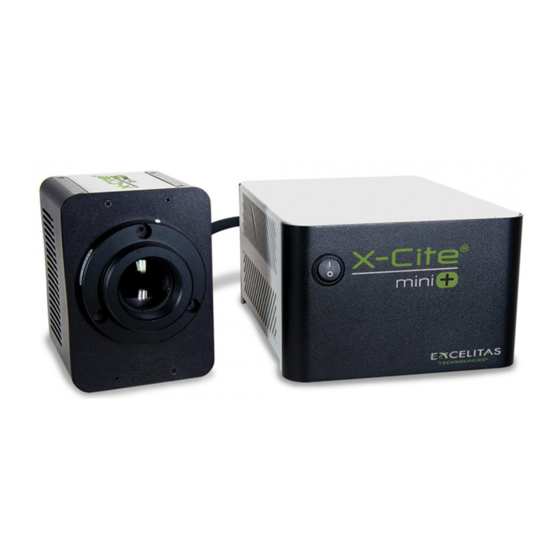
- Page 1 X-Cite mini+ User Guide ® Applies to X-Cite mini Series Models: XMPS XMPL XTMS XTML XT120Lm (X-Cite 120LEDmini)
- Page 2 X-Cite® mini+ User Guide 035-00587R rev. 5 Made in Canada Excelitas Canada Inc. 2020 All rights reserved No part of this publication may be reproduced, transmitted, transcribed, stored in a retrieval system or translated into any language in any form by any means without the prior written consent of Excelitas Canada Inc.
-
Page 3: Table Of Contents
Table of Contents Introduction ..........................5 Safety ............................6 Glossary of Symbols ........................6 Safety Precautions ........................6 Getting Started ...........................8 System Components ........................8 Installation/Set-up ........................9 Operation – Manual Control ..................... 12 The Basics ............................ 12 SpeedDIAL Home Screen......................13 SpeedDIAL Menu and Settings .................... - Page 4 China RoHS ..........................31 Australia - RCM ........................... 31 Warranty & Repairs ......................32 10.1 Warranty Terms .......................... 32 10.2 Returning equipment to Excelitas Technologies................. 32 Contact Information ......................33 11.1 General ............................33 11.2 Technical Support and Service ....................33 11.3...
-
Page 5: Introduction
X- ® Cite , formerly of Lumen Dynamics (which was acquired by Excelitas Technologies Corp. in November 2013) offers the Life Science and Analytical Instrumentation market a broad range of innovative lamp and LED fluorescence illumination and measurement solutions. -
Page 6: Safety
2 Safety 2.1 Glossary of Symbols Symbol Meaning CAUTION - Risk of danger: consult accompanying documents WARNING – Eye damage may result from directly viewing ultraviolet light. Protective eye shielding and clothing must be used at all times. Input/Output Signals Input Signal CAUTION –... - Page 7 9. Should this X-Cite® unit be used in a manner not specified by Excelitas Technologies, the protection provided by the equipment may be impaired.
-
Page 8: Getting Started
Hex Tool, 3mm c. USB Cable d. Power Cord e. Safety Precautions Booklet If any components are missing or appear damaged, please contact Excelitas Technologies immediately. Connection to LED Head AC in / Main Power Fuse Tray ON/OFF... -
Page 9: Installation/Set-Up
Rotating Dial Display Screen (LCD) Figure 3 SpeedDIAL 3.2 Installation/Set-up 1. Unpack a. Carefully unpack the unit and accessories from the shipping carton. b. When removing the LED Head and miniCUBE from the carton, ensure that both components are supported and there is always some slack in the cable. Excessive strain on the cable may damage or weaken the connection. -
Page 10: Figure 4 Installing Microscope Flange On Led Head
2. Install the Microscope Flange a. Remove protective wrap from the Microscope Flange, being careful not to touch the lens surfaces. b. Remove protective cap from LED Head. Never power up the unit with this cap installed – it can melt very quickly at high power settings and damage the unit. c. -
Page 11: Figure 5 Led Head And Arrow In Correct Position
4. Connect LED Head to Microscope a. Insert Microscope Flange portion of the LED Head into the light port on the microscope, and secure it using the hardware provided on the microscope. (Refer to relevant microscope user manual for complete instructions on mounting a standard epi- fluorescence lamphouse.) General guidelines: i. -
Page 12: Operation - Manual Control
5. Connect speedDIAL to miniCUBE a. Insert the mini DIN plug into the “Remote” port on the rear of the miniCUBE. Ensure the arrow mark on the connector is on top and centered. Note: Never force the connector – this can damage the pins. If connector does not insert smoothly, stop and check for bent pins. -
Page 13: Speeddial Home Screen
4.2 SpeedDIAL Home Screen LED Power Level speedDIAL Locked LED ON (via Computer) TTL Mode Enabled Figure 6 SpeedDIAL Home Screen Icons 4.3 SpeedDIAL Menu and Settings In addition to the intuitive intensity adjustment and illumination ON/OFF control, speedDIAL has several advanced settings and control options. -
Page 14: Speeddial Menu Structure
4.3.1 SpeedDIAL Menu Structure Dim Brig Color Exit Favo Int Enbl Spd Exit Enbl Time Exit Hand Srvc Hour SN Tmp1 Tmp2 S/W1 S/W2 ... -
Page 15: Favo - Favorite Intensity Setting
i. Select “Color” and scroll up /down through the options until desired color is on LCD. ii. Click dial to save selection and return to “LCD” menu. e. Select “Exit” to go back to the main menu, or press and hold dial to return to the home screen. -
Page 16: Uv - Uv Mode Control
iii. Click dial to save selection and return to “TTL” menu. To define the TTL timeout setting: i. Select the “Time” menu item. ii. Scroll through the time out options, which are: Never and 4 to 24 hours in half hour increments. -
Page 17: Operation - External Control
(e.g. 1142 hours will display as “1.1k hours”). The precise hour-by-hour data will continue to be available via USB communication. iii. Click dial to return to “Srvc” menu. c. To obtain the unit serial number: i. Select the “SN” menu option. ii. -
Page 18: Driver Installation (Via Zip File)
5.1.2 Driver Installation (via ZIP file) For these instructions, download the driver ZIP file from the Excelitas website: https://www.excelitas.com/product/x-cite-mini-compact-led-illumination-system a. Ensure X-Cite® mini+ is powered off. b. Ensure X-Cite® mini+ is connected to the computer with the USB cable. c. Prepare the driver files by extracting and saving the files into a folder on the desktop (or another easily accessible location). -
Page 19: X-Cite Control Panel - Tips For Use
a. Uninstall any previous versions of X-Cite® Control Panel/GUI. (Previous versions released under the EXFO name will not be automatically replaced by versions 1.1.0 or later, and may cause confusion.) b. Prepare the driver files (if not already done in previous section) by extracting and saving the files into a folder on desktop (or another easily accessible location). -
Page 20: Commercial Software Support
The lock icon will appear on the speedDIAL display in these cases. 5.1.7 Software Developer’s Kit (SDK) The command list for X-Cite® mini+ is available by request. To obtain the latest update, please contact Excelitas Technologies. X-Cite® mini+ User Guide 035-00587R rev. 5... -
Page 21: Ttl
5.2 TTL For high speed LED on/off control, TTL triggering can be used. The key thing to note about TTL control in the X-Cite® mini+ is: TTL mode MUST be enabled for the system to respond to a TTL signal. 5.2.1 TTL Mode TTL mode ensures that X-Cite®... -
Page 22: Ttl Signal And Led Status
5.3 Foot Pedal Control (Optional) For hands-free operation, a foot pedal can be used to manually turn the LED on and off. The foot pedal is an optional accessory and can be purchased separately from Excelitas Technologies. 1. Installing the foot pedal a. -
Page 23: Troubleshooting
6 Troubleshooting Organized by symptom, this section provides basic troubleshooting information for installation and set- up parameters. X-Cite® mini+ may be serviced by authorized technical personnel only. 6.1 Error Messages If X-Cite® mini+ detects a problem, an error message with one of the following codes will appear on the speedDIAL display. -
Page 24: Figure 10 Location And Removal Of Fuse Tray In Ac Receptacle
Figure 10 Location and Removal of Fuse Tray in AC Receptacle b. If either or both of the fuses are open, replace with the same type (4A, 250V). c. Note: To determine if a fuse is intact (i.e. OK) or open (i.e. blown), remove the fuse from the tray and check with a multi-meter set to resistance (Ω). -
Page 25: Low Illumination Intensity
6.3 Low Illumination Intensity 1. SpeedDIAL Setting Check: a. Verify that the LED intensity is set to a sufficient level. b. Verify that the LED Head is turning on. 2. Microscope Check: a. Verify that the Microscope Flange is appropriate for the microscope configuration. Note: Some flanges have the same mechanical fitting but different optics. -
Page 26: Routine Care And Maintenance
7 Routine Care and Maintenance 7.1 General X-Cite® mini+ is a very low maintenance system with no consumable components. By maintaining the following conditions, performance will be maximized and risk of future problems will be reduced. 1. Maintain a clean work area, keeping the X-Cite® mini+ air vents unobstructed. 2. -
Page 27: Thermal Management System
d. Repeat the previous step with a fresh portion of lens tissue (or new cotton swab) – this will help avoid recontamination of the optical surface and minimize the amount of cleaning required. e. Let solvent evaporate and verify that the optical surface is clean. Repeat cleaning steps as necessary. -
Page 28: Environmental - Operating Conditions
XT120Lm: 2.0A max /100V, 1.0A max/240V Input Surge With cold start 40A/115V, 80A/240V Protection Over load and over temperature Fuse Rating Dual fuse system: each fuse rated at F 4.0A 250V 5x20mm type located in AC receptacle 8.3 Environmental – Operating Conditions Ambient Temperature 10°... -
Page 29: Regulatory
If an application requires lower power levels, strategies to avoid fluctuations include: Increase power level, and reduce exposure time to compensate for brighter signal. Increase power level, and use a neutral density filter or iris in the microscope light train to reduce intensity to an appropriate level for the specimen. -
Page 30: Ce Marking
WARNING Changes or modifications not expressly approved by Excelitas Technologies could void the user’s authority to operate the equipment. 9.4 WEEE Directive... -
Page 31: China Rohs
In order to avoid the dissemination of those substances in our environment and to diminish the pressure on the natural resources, we encourage you to use the appropriate take-back systems. Those systems will reuse or recycle most of the materials of your end life equipment in a sound way. -
Page 32: Warranty & Repairs
10 Warranty & Repairs 10.1 Warranty Terms Excelitas Technologies warrants the original purchaser for a period of one (1) full year, calculated from the date of purchase, that the equipment sold is free from defects in material and workmanship. All repairs are warranted for 90 days. -
Page 33: Contact Information
2. Contact the nearest Excelitas Technologies Service Center to obtain a Return Material Authorization (RMA) number. For your convenience, RMA numbers can also be requested on- line at: techsupport@excelitas.com 3. Follow shipping instructions provided by the service technician. The unit should be returned in its original packaging if possible.
Need help?
Do you have a question about the X-Cite mini+ and is the answer not in the manual?
Questions and answers