Table of Contents
Advertisement
Quick Links
Advertisement
Table of Contents

Related Manuals for QEI ePAQ-9400


Summary of Contents for QEI ePAQ-9400
- Page 1 UG-1083 ePAQ-9400 User’s Guide December 2018...
- Page 2 The information in this document has been carefully checked and is believed to be accurate. However, no responsibility is assumed or implied for inaccuracies. Further more, QEI reserves the right to make changes to any products herein described to improve reliability, function or design. QEI does not assume liability arising out of the application or use of any product or circuit described herein;...
- Page 3 UG-1083 ePAQ-9400 Guide Revisions Revision Description Date Initial Release April 19, 2016 Client and Server updates. April 29, 2016 Formatting Update June 7, 2017 Updated QEI Address Dec. 10, 2018 ePAQ-9400 User’s Guide Revisions...
-
Page 5: Table Of Contents
Status Keying Source ............17 Status Connection Diagram ..........17 10 Firmware / Software ............... 18 10.1 Communications Protocols ..........18 11 Mechanical Outline ..............19 12 Other Related Documentation ..........20 13 Ordering Information .............. 20 ePAQ-9400 User’s Guide Contents... - Page 6 UG-1083 ePAQ-9400 14 Test Panel ................21 14.1 Introduction ................ 21 14.2 Requirements ..............22 14.3 Functional Test Capability ..........22 14.3.1 Analog Monitoring ..........22 14.3.2 Status Monitoring ..........23 14.3.3 Accumulator Monitoring ........23 14.3.4 Control Operation ..........23 14.3.5 Set Point Operation ..........
-
Page 7: Description
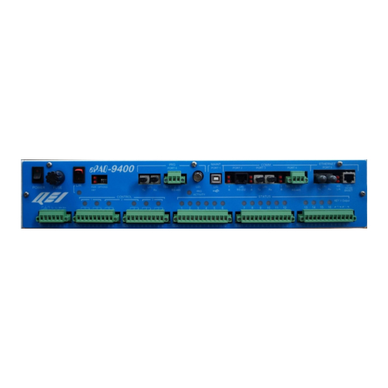
UG-1083 ePAQ-9400- 1 Description The ePAQ-9400 is a communications gateway and distributed I/O module, in a 19 in. 2U enclosure (rack-mount or DIN-mount). It provides 16 status inputs and 3 momentary or latching control points. Hardware communications ports include RS-232, Fiber, RS-485, and 10/100 Ethernet (via copper or Fiber). -
Page 8: Specifications
UG-1083 O-9100 User’s Guide UG-1062 2 Specifications General Description Microprocessor Atmel ARM9 32-bit Processor. Communications Ports Port 1: Maintenance Interface Connector Type B (J3) Port 2: RS-232 Interface RS-232 TX, RX, RTS, CTS & COM. Protocols Asynchronous Bit or Byte Oriented Bit Rate 1200 to 115.2Kbps... - Page 9 17.3” W x 3.5” H x 5.0” D without mounting brackets Mounting Dimensions 19.0” W x 3.5” H x 5.0” D w/ rack mounting brackets 17.3” W x 3.5” H x 5.3” D w/ DIN mounting brackets Copyright © 2016 QEI. Specifications...
-
Page 10: Input Power Connections
O-9100 User’s Guide UG-1062 3 Input Power Connections The ePAQ-9400 accepts a variety of input voltage sources, such as 12, 24, 48, and 125Vdc. The unit may also be powered by 120, 240 or 277Vac. Input power connections are made at terminal block TB1:... -
Page 11: Dip Switches
I = Remote O = Local (L/R Led will be on, indicating local mode) FUSE 48/125V Input = 1 Amp Slo-Blo 250VAC (QEI P/N 10-003669-001) 12/24V Input = 2 Amp Slo-Blo 250VAC (QEI P/N 10-003669-026) Dip Switches One bank of four DIP switches is available through the front panel. Dip switches are used for application specific options (see the appropriate ConfigWiz 2.0 addendum... -
Page 12: Jumper Settings
UG-1083 O-9100 User’s Guide UG-1062 Jumper Settings JUMPER Function Watchdog. Factory installed jumper on Communications Board (near CPU board). Must be present for proper operation. Do not remove. 6 LED Indications Control LEDs CONTROL There are six LEDs arranged as three Trip/Close pairs for the three control points. -
Page 13: L/R (Local/Remote) Led
POWER FUSE LED Name Function “Local” mode indication LED. This LED turns on whenever the L/R L / R (Local/Remote) switch is placed in the “Local” position. In Local mode, controls are disabled. Copyright © 2016 QEI. LED Indications... -
Page 14: Logic Pwr And Heartbeat Leds
UG-1083 O-9100 User’s Guide UG-1062 Logic Pwr and Heartbeat LEDs A dual LED array indicates logic power (upper LED) and CPU activity, or heartbeat (lower LED): LED Name Function Upper LED indicates CPU logic power is active when lit. -
Page 15: Communications Ports
This port is a standard USB type B port for connection to a PC. It is used as a Maintenance Port, to program and troubleshoot the ePAQ-9400. Using a PC with a USB port and a straight USB type A-B cable, the ePAQ can be accessed in one of two ways, 1) via ConfigWiz 2.0, to download configurations and flashload program... -
Page 16: Port 3 (J5) : Fiber Optic
UG-1083 O-9100 User’s Guide UG-1062 The Push-to-Talk (PTT) signal can be used to key an external radio, if needed. This pin is in the form of an open collector output. Port 3 (J5) : Fiber Optic This generic fiber optic serial communications port has one transmitter (TX) and one receiver (RX). -
Page 17: Port 5 (J6 Or J7): Ethernet 100Basefx / 100Baset
RJ45 jack for CAT5 cable (J7). It supports either 100BaseFX Ethernet over fiber, or 100BaseT Ethernet over copper. Do not use both connectors at once. ETHERNET PORT 5 (J7) (J6) 10/100 BASET J6 ST Jacks Signal Name Transmit data output. Received data input. Copyright © 2016 QEI. Communications Ports... -
Page 18: Port 6 (J1 Or J2 Or Tb4): Irig-B Time Sync
Port 6 (J1 or J2 or TB4): Irig-B Time Sync This single port accepts input from an Irig-B receiver for time syncing the internal EPAQ-9400 timeclock. Time sync Input can come from an either an unmodulated or modulated Irig-B source. -
Page 19: Controls
Trip, the other set for Close) at the terminal blocks: For the illustration above, T= Trip LED, C = Close LED. The relay contact schematics above the terminal blocks are shown with relays in the un-energized state. Copyright © 2016 QEI. Controls... -
Page 20: Momentary Form 1X Or 1A Controls
UG-1083 O-9100 User’s Guide UG-1062 Momentary form 1C connections: Connection Name TB2A-1 Control Point #1 Trip COM TB2A-2 Control Point #1 Trip N.O. TB2A-3 Control Point #1 Trip N.C. TB2A-4 Control Point #1 Close COM TB2A-5 Control Point #1 Close N.O. -
Page 21: Latching Form 1C Control Connections
Latching control points use a single set of form 1C contacts on the terminal block. For the latching illustration above, T= Trip LED, C = Close LED, and the relay contact schematics are shown with relays in the “tripped” state. Copyright © 2016 QEI. Controls... -
Page 22: Status
Control Point #3 COM TB2B-8 Control Point #3 N.O. TB2B-9 Control Point #3 N.C. 9 Status The ePAQ-9400 has sixteen status inputs. Various keying voltage/source options are available. See the ordering information to choose the appropriate status keying configuration. STATUS Connection Name... -
Page 23: Status Keying Source
48Vdc, then the status keying source will be 48Vdc. No keying source provided. TB3C-9/10 and TB3C-11/12 may be used as tie points for the user provided keying voltage source. Status Connection Diagram Copyright © 2016 QEI. Status... -
Page 24: Firmware / Software
O-9100 User’s Guide UG-1062 10 Firmware / Software An ePAQ-9400 Program Link (firmware) is required to be loaded onto the ePAQ- 9400 to provide its operation. Configuration is performed using QEI’s “ConfigWiz 2.0” RTU configuration program, which is PC software available on CD. A special ePAQ-9400 Template is required to configure the ePAQ-9400 using the ConfigWiz 2.0 software. -
Page 25: Mechanical Outline
UG-1083 ePAQ-9400- 11 Mechanical Outline Copyright © 2016 QEI. Mechanical Outline... -
Page 26: Other Related Documentation
UG-1083 O-9100 User’s Guide UG-1062 12 Other Related Documentation UM-2018 ConfigWiz 2.0 User’s Guide w/ ePAQ-9400 Addendum 13 Ordering Information Designation: ePAQ-9400-A/BB/C/D/E/F/MODXX Parts List: 40-058178-ABBCDEF A = Input Voltage Option 12Vdc/24Vdc 48Vdc to 125Vdc, 120/240/277Vac (Note 4) BB = Status Keying Input and Keying Voltage Source... -
Page 27: Test Panel
The proper keying voltage option must be selected to match the customer provided keying voltage source. Note 2: Internal non-isolated keying voltage source is tapped from the ePAQ-9400 input voltage source, and appears at terminal block TB3C right-most end terminals. The proper keying option must be chosen to match the ePAQ-9400 input voltage option. -
Page 28: Requirements
USB type A-B cable (for local connection.) A server point map list is also required. The list indicates the function of each data point. A server point map is generated by QEI’s “ConfigWiz 2.0” configuration software. 14.3 Functional Test Capability... -
Page 29: Status Monitoring
On/Off status of every point on as many as four (4) selected 16-point status groups can be displayed at a time as they are being processed within the ePAQ-9400 Subsystem. Status points displayed can consist of the 16 hardware status point connections (ePAQ terminal blocks TB3A, TB3B, and TB3C), as well as other status points within the overall subsystem. -
Page 30: Installing The Usb Driver
If you have previously installed the driver, you can skip to the next section. 1) Power up the ePAQ-9400 and wait for the heartbeat (HBT) Led to begin flashing. 2) Connect a USB type A-B cable between the ePAQ and PC. -
Page 31: Local Test Panel Connection (Usb Port)
1) Turn on the ePAQ power. Verify that the front panel heartbeat (HBT) LED begins flashing. 2) Connect the USB cable between the ePAQ USB port 1 (J3) and the PC. 3) Start the ePAQ-9400 HyperTerminal session. 4) Hit <enter> several times. 5) You should see a ePAQ prompt appear on the HyperTerminal screen. -
Page 32: Help For Test Panel Commands
Note that the user prompt line above reads: ePAQ-9400_A> _ The prompt indicates which configuration file is in use. The ePAQ-9400 can contain up to two stored configurations (A and B) for use as backups. Using the test panel SAVE and RESTORE commands, each configuration file can be stored in non- volatile memory, and recalled when needed. -
Page 33: Date And Time Commands
Type in RA (space) and the number or numbers of analog points, not necessarily in any order. Each number must be followed by a space. Points begin with point number 0 (zero). The values are displayed as decimal integers. The displayed values are continuously updated. Example entry: Copyright © 2016 QEI. Test Panel... -
Page 34: Reading Status Values (Rs)
UG-1083 O-9100 User’s Guide UG-1062 RA 5 2 3 4 1 Example display: +25116 +0136 -12000 +0050 +0246 NOTES Analog points will be displayed as 16-bit values (default). To display points as 12-bit values, type 12bit <enter> before using the RA command. -
Page 35: Reading Accumulator Values (Rc)
Each number must be followed by a space. Point numbers begin with point number 0 (zero). Example entry for accumulator points: RC 7 10 14 15 Display: 00230 00010 01462 00483 Copyright © 2016 QEI. Test Panel... -
Page 36: Relay Control
UG-1083 O-9100 User’s Guide UG-1062 NOTE The display will indicate in decimal format and display the actual count, as sampled (15-bit values). When additional accumulator points are to be examined, press the ENTER key, the accumulator points previously entered will scroll upwards to the next line on the display and all values will be frozen. -
Page 37: Off Relay Operation (Cf)
The test panel displays (example): Port Baud User RtsCts RtsHold ---------------------------------------------------------------------------------------- RS232 9600 0000 none 0 RS485 9600 8200 Dnp/QUICS 0 Fiber 9600 0000 none 0 RS485-B 9600 0000 Irig 0 Fiber-B 9600 0000 Irig 0 Copyright © 2016 QEI. Test Panel... -
Page 38: Prx Command
UG-1083 O-9100 User’s Guide UG-1062 14.12.2 PRX Command The Test Panel can be used to track communications on any serial or Ethernet port. Since the output on the display may be difficult to read due to the communication speed, it may be necessary to save the data in a file (recording file), which can be examined later. -
Page 39: Displaying Dip Switch States (Dip)
To display the version of software residing in the ePAQ, type VER <enter>. Example VER <enter> Display QEI ePAQ-9400 Link:80-009XXX-XXX 8/22/08 Chksum: 6320d4ca 14.15 TP Command This command invokes a software monitor, which is useful in diagnosing different types of problems. -
Page 40: Soe
UG-1083 O-9100 User’s Guide UG-1062 11/10/2005 13:32:29.495 [1] Panel0Pt1 11/10/2005 13:32:29.495 [0] Panel0Pt0(status0) OFF The header indicates how many events are available, and also whether the events are stored in RAM or in BBRam (Events are stored in BBRam if battery-backed memory is available). -
Page 41: Sec Security Logger
10/07/2008 11:14:53.791 User bob Logged in 10/07/2008 11:09:16.438 User bob Logged in 10/07/2008 10:41:42.229 User bob Logged in 10/07/2008 10:33:10.479 User bob Logged in 10/07/2008 09:26:11.099 User bob Logged in 10/04/2008 16:42:31.146 User bob Logged in Copyright © 2016 QEI. Test Panel... -
Page 42: Eth Command
IP: 192.168.0.95 NM: 255.255.255.0 GW: 192.168.0.1 Cfg: 1 0 0 14.20 PROFILE Command Enables software profiler, used mainly for QEI debug. Lists amount of processor usage per task. ePAQ-9400_A> PROFILE Profiling at 10000 msec Intervals Exec Dnp/QUICS SOE Logger 03%... -
Page 43: Save Command
14.21 SAVE <A or B> Command The ePAQ-9400 can contain up to two stored configurations (A and B) for use as backups. Using the test panel SAVE and RESTORE commands, each configuration file can be stored in non-volatile memory, and recalled when needed. Using ConfigWiz 2.0, the user can assign a unique ID string for each configuration file.
Need help?
Do you have a question about the ePAQ-9400 and is the answer not in the manual?
Questions and answers