Table of Contents
Advertisement
Advertisement
Table of Contents

Related Manuals for Xtreme XR842


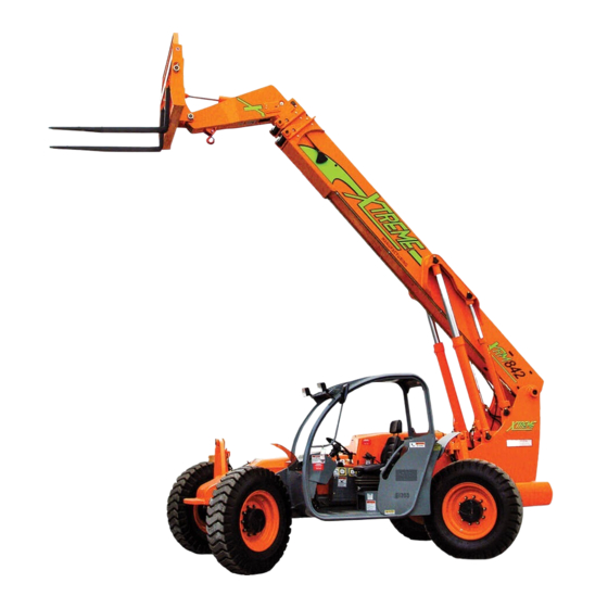
Summary of Contents for Xtreme XR842
- Page 1 Operation & Safety Manual PN 24904-000 Operation Manual...
- Page 2 PN 24904-000 REV 01 OCTOBER 2015 AUTHOR: OVY LUNGU © 2015 XTREME MANUFACTURING. ALL RIGHTS RESERVED Operation Manual...
-
Page 3: Table Of Contents
Table of Contents Table of Contents Description Page Description Page Operator Seat Controls Introduction Weight Suspension Lever General Lumbar Support Replacement Manuals Fore and Aft Adjustment Lever Model/Serial Plate Backrest Angle Adjustment Lever Orientation Seat Belt Safety Rear View Mirrors Safety Disclaimer Controls and Indicators Signal Words... - Page 4 Table of Contents Table of Contents Description Page Description Page Operation Standard Carriage Operation Pre-Operation Inspection Fork Positioning Carriage Operation Pre-Operation Inspection Checklist Quick Attach System Functional Tests Load Handling Operator Maintenance Boom Lift Point Before Starting Forklift Suspended Loads Starting Forklift Pick Up a Load Normal Starting...
-
Page 5: Introduction
RIGHT Replacement Manuals Replacement manuals for the XR842 forklift can be obtained by contacting our parts department by phone or visiting our website: Xtreme Manufacturing Phone: (800) 497-1704 LEFT www.XMFG.com... -
Page 6: Safety
Safety Safety Disclaimer Signal Words Xtreme Manufacturing reserves the right to make technical Signal words are the word or words that call attention to changes for product improvement. This manual may contain the safety sign and designate a degree or level of hazard illustrations and photographs (for demonstration purposes), seriousness. - Page 7 Safety Read Operator Read Maintenance General Safety Manual Before Manual Before Alert Symbol Operating This Working On Telehandler This Telehandler Read Material DO NOT OPERATE! Know First Aid Safety Data Instructions And/ Telehandler Down Sheets (MSDS) For Or Locations On For Service Or Chemicals And Work site...
- Page 8 Safety DO NOT DO NOT Fasten Allow Riders Jump While Seat Dismounting On Auxiliary Belt The Telehandler Attachments Set Parking DO NOT Allow DO NOT Allow Brake To OFF Riders On Telehandler Riders On Or In Disengage Frame Or Fenders The Operator Cab Parking Brake Set Parking Brake...
-
Page 9: Employer Responsibility
Safety Employer Responsibility Operator Qualifications Under Occupational Safety and Health Administration (OSHA) Operators must be in good physical and mental condition, rules, employers are required to train workers about hazards with appropriate reflexes, reaction time, vision, depth related to operating and maintaining the forklift. Successful perception, and hearing. -
Page 10: Mounting/Dismounting
Safety Warning Mounting/Dismounting • Operate the forklift only on firm, stable surfaces. Holes, Warning obstructions, debris, loose fill, and other work site hazards could result in death or serious injury. Failure to use proper safety procedures when mounting • DO NOT allow bystanders in the work area. and dismounting the forklift could result in death or serious •... -
Page 11: Before Starting Forklift
A brief description of controls, indicators, Keep the Operation and Safety Manual and instruments is provided as a convenience on the forklift at all times. Contact Xtreme for the operator. These descriptions DO NOT Manufacturing for replacement manuals. provide complete operation instructions. -
Page 12: Operation Safety
Safety Warning Warning Operators must be properly trained and Use of the frame sway control with the boom qualified to operate this specific forklift. raised above horizontal could cause tip over Know the location, learn the specific purpose, resulting in death or injury. Always use the and demonstrate safe and proper use of all frame sway control to level the forklift controls, instruments, indicator lights, and... - Page 13 Safety DO NOT shift through multiple gears with a Warning single turn of the gear select lever. Allow the engine speed to slow down before shifting to DO NOT use the forklift as a work platform the next lower gear. Improper use of the gear or personnel carrier.
-
Page 14: Load Safety
Safety Follow appropriate procedures to prevent • Reposition the forklift if it cannot be leveled using the sudden changes in forklift speed that could frame sway control. result in death or serious injury. • DO NOT enter or exit a tilted cab. •... -
Page 15: Attachments
Safety Attachments Forklift Maintenance Warning Warning Improper connection of an auxiliary attachment could Follow manufacturer’s instructions proper result in death or serious injury. Attachments not locked maintenance to make sure the forklift continues to meet into place can become unstable and fall on the operator or manufacturer’s specifications. - Page 16 Safety It is possible for the forklift to move suddenly ately. Flushing must begin immediately to avoid per- when the brakes are released, which could manent eye tissue damage. result in death, serious injury, or property • Internal contact - Drink large quantities of water or milk damage.
-
Page 17: Dead Engine Towing
Safety Dead Engine Towing Parking Brake Release (Front Axle) Warning Block all four (4) wheels. Failure to do so could result in death or serious injury from forklift roll away. 1. Block all four wheels to prevent the forklift from moving once the parking brake is disabled. -
Page 18: Labels
Labels Labels Left Side View Fig 6. Label Legend (Left Side) Right Side View Fig 7. Label Legend (Right Side) Operation Manual Operation Manual... - Page 19 Labels Front View Rear View Fig 8. Label Legend (Front) Fig 9. Label Legend (Rear) Cab View Fig 10. Label Legend (Cab) Operation Manual Operation Manual...
- Page 20 Boom Angle Indicator 17019-000 Load Chart, 12ft Truss with Winch 18041-001 Warning, Pinch Point Hazard 17071-000 Load Chart, Personnel Platform 18042-000 Xtreme logo (chassis) 17128-000 Load Chart, Sling Mount 18066-001 Caution, Crushing Hazard 17180-000 Load Chart, Boom Hook 18067-100 Frame Sway Handle 18334-001 Handle Auxiliary Controls (Opt.)
-
Page 21: Replacement Labels
Labels Replacement Labels Replacement labels can be obtained by contacting Xtreme Manufacturing at (800) 497-1704. Please have the correct label number available when you call. Parking Brake Volts Fuel Coolant Hourmeter 702-636-2969 Rear Axle 800-497-1704 Lights Centered Crab Steering Declutch... - Page 22 Labels 7) 18015-001 8) 18016-001 9) 18017-001 10) 18018-001 11) 18018-002 12) 18019-001 Operation Manual Operation Manual...
- Page 23 Labels 13) 18020-001 14) 18021-001 15) 18022-001 16) 18023-001 17) 18025-001 18) 18026-001 Operation Manual Operation Manual...
- Page 24 Labels 19) 18027-001 20) 18031-001 WARNING 21) 18032-001 22) 18033-100 23) 18347-000 24) 18039-000 Operation Manual Operation Manual...
- Page 25 Labels 25) 18041-001 26) 18042-000 27) 18066-001 28) 18067-100 FULL 18334-001 18069-000 29) 18334-001 30) 18069-000 Operation Manual Operation Manual...
- Page 26 Labels 31) 18082-001 32) 18083-001 33) 18086-002 34) 18090-001 35) 18300-001 36) 18312-000 Operation Manual Operation Manual...
- Page 27 Labels 37) 18315-000 38) 18043-000 39) 18044-000 40) 18046-000 41) 18047-000 42) 18048-000 Operation Manual Operation Manual...
- Page 28 VEHICLES EQUIPPED CENTER WITH FOAM FILLED TIRES ONLY. 702-636-2969 • 800-497-1704 REACH FT 17015-000 52) 17015-000 XR842 LOAD CHART - 12 FT TRUSS BOOM 18311-000 48) 18311-000 LOAD RATINGS TRUSS WEIGHT SHOWN ARE FOR 550 LBS NOMINAL VEHICLES EQUIPPED CG X = 48.33 IN...
- Page 29 Labels XR842 LOAD CHART - 15 FT TRUSS BOOM XR842 LOAD CHART - 3 FT TRUSS BOOM WITH WINCH LOAD RATINGS TRUSS LOAD RATINGS TRUSS WEIGHT SHOWN ARE FOR WEIGHT SHOWN ARE FOR 650 LBS NOMINAL VEHICLES EQUIPPED 600 LBS VEHICLES EQUIPPED CG X = 65.78 IN...
-
Page 30: Features
Features Features Standard Equipment Optional Equipment Feature Description Feature Description Boom Universal quick attach head Tires Foam-filled Three (3) section boom Hydraulics Auxiliary hydraulic circuit with quick attach Boom equipped with heavy duty boom rollers Attachment tilt switch Chassis Rear axle stabilization Frame sway control handle 1-1/4 inch main frame plate Frame sway override switch... -
Page 31: Specifications
Brakes ....Inboard Wet Disc Suspension Seat Parking Brake ..SAHR Quick Attach (Common Fit) Xtreme Service Accessibility Tires Attachments Tires (Standard Eq) Foam Filled 13.00 x 24 E3... -
Page 32: Operator Cab
Operator Cab Operator Cab Accessory Outlet A 12 volt accessory outlet is provided as a power source for Warning personal items, such as a radio or cell phone. A brief description of controls, indicators, and instruments is provided as a convenience for the operator. -
Page 33: Service Brake Pedal
Operator Cab Service Brake Pedal Horn Button Press the service brake pedal to slow or stop the forklift. The Press the horn button to sound the horn. service brake pedal activates the service brakes on all four (4) wheels. Figure 16. Horn Button Figure 14. -
Page 34: Weight Suspension Lever
Operator Cab Weight Suspension Lever Fore and Aft Adjustment Lever Rotate the weight suspension lever to increase or decrease the Pull the fore and aft adjustment lever outward from the seat seat cushion suspension based on the weight of the operator to release the seat lock. -
Page 35: Seat Belt
Operator Cab Before starting the engine, adjust the seat for position and Seat Belt comfort (refer to the Operator Seat section of this manual) and then adjust the seat belt as follows: Warning 1. Grasp the free end of the seat belt (located on the left side of the seat) and make sure the belt webbing is not twisted or Always check the condition of the seat belt entangled in any portion of the seat assembly. -
Page 36: Controls And Indicators
Operator Cab One (1) rear-view mirror is mounted on the right side of the chassis. Figure 25. Travel Select Lever Figure 24. Chassis-Mounted Mirror Gear Select Switch The Gear Select switch has a twist grip handle with three (3) Controls and Indicators positions: 1 - FIRST, 2 - SECOND, and 3 - THIRD. -
Page 37: Parking Brake Switch
Operator Cab Parking Brake Switch Hydraulic Oil Temperature Indicator The Parking Brake switch (A) has two (2) positions: ON and The Hydraulic Oil Temperature Indicator illuminates when the OFF. oil temperature is above 180°F. If the Hydraulic Oil Temperature Indicator illuminates, stop and idle the engine to allow time for cooling. -
Page 38: Engine Warning Indicator
Operator Cab Engine Warning Indicator Hour Meter The Engine Warning Indicator illuminates for five (5) seconds The hour meter indicates and records engine operating hours when the key switch is moved to the RUN position. After that and has a total readout of 9,999.9 hours. Use the hour meter period, a steady LED indicates the engine is operating normally to establish a forklift maintenance schedule. -
Page 39: Fuel Gauge
Operator Cab Fuel Gauge Coolant Gauge The fuel gauge indicates the quantity of fuel in the fuel tank. The coolant gauge indicates the temperature of the coolant The total capacity of the fuel tank is 48 gallons. in the engine cooling system. After starting the forklift, allow time for the coolant temp gauge pointer to begin to move before operating the forklift. -
Page 40: Turn Signal And Hazard Switches
Operator Cab Turn Signal and Hazard Switches Steering Select Switch The optional Turn Signal Switch controls the turn signals Warning (toggle left or right). The optional Hazard Light Switch flashes all four (4) turn signals (toggle up or down). DO NOT change steering modes until the forklift slows or comes to a complete stop. -
Page 41: Boom Control
Operator Cab • When the Declutch switch is set to OFF, the transmission remains engaged when the travel select lever is set to either FORWARD or REVERSE. Figure 40. Declutch Indicator / Declutch Switch Boom Control The boom control handle has variable motions from the center position that control boom and tilt functions. -
Page 42: Attachment Tilt Switch
Operator Cab Attachment Tilt Switch The Attachment Tilt Switch located on the top of the boom control handle controls attachment tilt functions. Figure 42. Boom Control Handle Functions Figure 44. Attachment Tilt Switch (1) Attachment Tilt Down (2) Attachment Tilt Up The Attachment Tilt Switch: •... -
Page 43: Auxiliary Attachment Control
Operator Cab Auxiliary Attachment Control The Auxiliary Attachment Control lever controls the functions of approved optional attachments that can be mounted to the forklift and require hydraulic supply for operation. Figure 45. Frame Sway Control Handle Frame Sway Control Handle Function Purpose Frame sway right... -
Page 44: Boom Angle Indicator
Operator Cab Boom Angle Indicator Frame Level Indicator The frame level indicator is mounted on the upper right The boom angle indicator is located on the left side of the corner of the operator’s cab. The frame level indicator allows boom and is visible from the operator’s seat. -
Page 45: Forklift Lifting Points
Warning Forklift Lifting Points Ensure that no one is in the work radius before The XR842 lifting points are shown below. The forklift should lifting forklift to avoid crushing hazard. only be lifted if lifting points are installed. MODEL: XR842... -
Page 46: Operation
Operation Caution Operation Contact with hot surfaces and the exhaust Pre-Operation Inspection pipe after the forklift has been operated could result in serious personal injury. To perform the pre-operation inspection make sure the forklift is NOT running, the engine is cool, the forklift is parked on level ground, the boom is completely retracted, and the frame is level. - Page 47 Operation Warning Warning Wear eye protection when starting a forklift with jump start cables. Improper jump start procedures could cause the battery to ex- plode, which could result in death or serious injury. Lead-acid batteries produce flammable and potentially ex- •...
-
Page 48: Pre-Operation Inspection Checklist
Operation Pre-Operation Inspection Checklist Walk around the ENTIRE forklift while visually performing the pre-operation inspection. Check that “Do Not Operate” tags have not been placed on the forklift. Check that load capacity charts are legible. Check that frame level indicator is working properly. Check condition and operation of the seat belt and mounting hardware. -
Page 49: Functional Tests
Operation Operate the boom control handle forward and Functional Test Checklist backward to lower and raise boom. Operate the boom control handle left and right to Warning retract and extend boom. Operate the attachment tilt thumb stick up and down Perform a pre-operation inspection and func- to tilt the attachment. -
Page 50: Operator Maintenance
Operation Operator Maintenance Figure 56. Check Engine Oil Level. Add Engine Oil (API CJ- Figure 53. Check Hydraulic Oil Sight Gauge 4), If Necessary. Figure 54. Add Hydraulic Oil, if Necessary Figure 57. Check Battery Case and Terminals Figure 55. Check Coolant Reservoir Level. Add Coolant, if Figure 58. -
Page 51: Before Starting Forklift
Operation Before Starting Forklift Warning Failure to use proper safety procedures when mounting and dismounting the forklift could result in death or serious injury. • Keep steps clear of dirt, mud, snow, ice, debris, and oth- er hazards. Face the forklift for mounting or dismount- ing. -
Page 52: Starting Forklift
Operation Starting Forklift Normal Starting Warning To prevent death, serious injury, or property damage, the operator must be seated with seat belt fastened, arms, legs, and head com- pletely inside the Rollover Protection Struc- ture/Falling Object Protection Structure Figure 62. Turn Key in Ignition Switch to START (ROPS/FOPS), the travel select lever in NEUTRAL, and the Parking Brake switch ON (engaged) BEFORE starting the forklift. -
Page 53: Jump Starting
Operation • Never jump start a frozen battery, as it can explode. Let Jump Starting the battery thaw out before charging. • NEVER jump start the forklift when travel select lever is Jump Start or replace the battery of the forklift when the in gear, which can cause the forklift to lurch forward or battery is discharged to the point that it will not crank the backward, and could result in death, serious injury, or... -
Page 54: Forklift Travel
Operation NOTE: If the engine fails to start on the first try, wait until the Crab Steering engine and starter come to a complete stop before cranking Crab steering allows all four (4) wheels to turn the engine again. in the same direction as the steering wheel, allowing the forklift to move “sideways”. -
Page 55: Starting Travel
Operation To shift gears rotate the gear select lever to the next gear Starting Travel while the forklift is traveling. • Use first gear (1) for highest torque and pulling power. Warning • Use higher gears for higher ground speed. •... -
Page 56: Stopping Travel
Operation The low brake pressure indicator illuminates if the hydraulic Warning brake oil pressure gets low. If the low brake pressure indicator is illuminated, stop the forklift, follow proper shut down To prevent death, serious injury, or property procedures, tag the forklift with “Do Not Operate” tags, and damage, apply service brakes until the forklift have a qualified mechanic service or repair the forklift BEFORE comes to a complete stop, move travel select... -
Page 57: Fuel Types
Xtreme Manufacturing assumes no climate to prevent hard starts and excessive smoke. liability for any third party attachment that would alter the center of gravity or stability. -
Page 58: Standard Carriage Operation
Operation Fork Positioning Carriage Operation Caution Do not adjust forks when Fork Positioning Carriage is load- ed. Adjusting forks when carriage is loaded may result in loss of load or carriage damage. Always use the Fork Posi- tioning control handle to adjust the forks BEFORE loading the carriage. -
Page 59: Quick Attach System
Operation Figure 72. Quick Attach Couplers For Hydraulic Systems. Figure 73. Drive Forklift Forward to Align Pivot Pins (A) with (A) Female Coupler. (B) Male Coupler. Attachment Hooks (B) 4. Raise the boom until pivot pins (A) have seated fully in at- Quick Attach System tachment hooks (B). - Page 60 Operation Figure 77. Insert Quick Attach Pin Through Attachment and Quick Attach Adapter. 8. Release the quick attach lock lever and make sure it has lowered and seated itself in groove (A) of the quick attach pin. Figure 75. Tilt Attachment To Align Holes Between Quick At- tach Adapter (C) and Attachment (B).
- Page 61 Operation 9. Connect the quick attach couplers (this only applies to at- 7. Raise the quick attach lock lever. tachments with a quick attach hydraulic system). Figure 81. Quick Attach Lock Lever 8. Pull out the quick attach pin at the bottom of the quick attach adapter.
-
Page 62: Load Handling
Operation 10. Tilt and lower boom until pivot pins (A) have disconnected Keep the forklift, attachments, and loads a from attachment hooks (B). safe distance from electrical power lines. • Remain at least 10 feet (3 meters), plus an additional 0.4 inches (10 millimeters) for each 1,000 volts over 50,000 volts, from active power lines and other power sources. -
Page 63: Boom Lift Point
Operation • Adjust the load as necessary, especially for nonstandard Suspended Loads loads. • Use caution when handling loose material that can fall Avoid carrying a suspended load. If necessary, into the cab. secure the load by attaching it to the forklift •... -
Page 64: Carry A Load
Operation Carry A Load Load Shift Carry the load as low as possible while maintaining good If the load shifts, stop the forklift immediately. ground clearance and visibility. Lower and adjust the load to center its weight. Back away slowly. If the load shift is too great for adjustment, rearrange the To travel with a load, use first gear (1) for highest torque load before attempting to move the forklift. - Page 65 Operation Provide a means so that the platform can only be centered manufacturer’s instructions. laterally on the forklift and retained against the vertical Make sure the platform, carriage, and forks are secured to face of the forks, carriage, or lifting mechanism. prevent them from pivoting from side to side.
-
Page 66: Load Capacity Charts
Operation 20. Use of railings, planks, ladder, etc. on the platform for purpose of achieving additional reach or height is prohibited. 21. Before elevating personnel, the area around and under the work platform should be marked to warn anyone on the ground that overhead work is being done. - Page 67 • Distance from front tires where load will be placed the boom extend letter “E” showing. XR842 LOAD CHART - STANDARD CARRIAGE LOAD RATINGS SHOWN ARE FOR VEHICLES EQUIPPED WITH FOAM FILLED TIRES ONLY.
-
Page 68: Frame Leveling
Operation level condition. Always frame sway the forklift right or left un- Frame Leveling til the indicator shows 0° (level). Warning Use of the frame sway control with the boom raised above horizontal could cause tip over resulting in death or injury. Always use the frame sway control to level the forklift BEFORE raising the boom above horizontal. -
Page 69: Preventive Maintenance
Preventive Maintenance Check condition and tension of drive belts (use Preventive Maintenance tension meter to check belt tension) Lubricate front and rear drive shaft grease fittings Establishing a Maintenance Program Lubricate front and rear axle grease fittings The hour meter displays elapsed engine operating hours and has a total readout of 9,999.9 hours. - Page 70 Preventive Maintenance After Every 250 Hours of Operation Check specific gravity of engine coolant Comply with 50-Hour Maintenance Requirements Replace transmission fluid and filters Change engine oil and filter Replace hydraulic reservoir air breather Check air filter (replace if necessary) Replace hydraulic return line filter Check tension and condition of drive belts (use Replace hydraulic high-pressure filter...
-
Page 71: Boom Emergency Lower Down Valve
Lockout / Tagout Boom Emergency Lower Down Valve Both of the lift and extend cylinders are equipped with a needle valve which allows the cylinder to retract without the direct assist of the machine’s hydraulic power. This feature is intended to be used only in the event of total loss of engine or hydraulic pump failure with an elevated boom. -
Page 72: Do Not Operate - Accident Prevention Tags
Lockout / Tagout Do Not Operate - Accident Prevention Tags Before beginning any maintenance or service, place a Do Not Operate Tag on both the starter key switch and the steering wheel, stating that the forklift should not be operated. Do Not Operate Tags, which can be cut out and used, are included at the end of this manual. -
Page 73: Do Not Operate Tags
Lockout / Tagout Do Not Operate Tags Operation Manual Operation Manual... - Page 74 Warranty Xtreme Manufacturing Product Warranty Policy 1) Xtreme Manufacturing warrants, its authorized sales and service centers (herein referred to as “SSC”), new product(s) the mainframe and chassis weldments shall be free from defect in material and workmanship for the period of 10 years or 10,000 hours whichever comes first. The boom weldment and boom rollers shall be free from defects in material and workmanship for the period of 5 years or 5,000 hours whichever comes first. The powertrain assemblies consisting of engine, transmission and drive axles and all other components not listed above shall be free from defects in material and workmanship for the period of 2 year or 2,000 hours after date of delivery. This warranty is made to the original owner of the new product(s) and is transferable for the duration of the coverage period, to the subsequent owner with prior written approval from Xtreme Manufacturing (see limitations). 2) Machines may be held in an authorized Distributor/ SSC’s stock for a maximum period of six (6) months from the date of shipment from Xtreme, before the warranty period is automatically initiated on each machine. 3) It is the responsibility of the Distributor/SSC to complete and return to Xtreme Manufacturing a Pre‐delivery Inspection Record, Warranty Registration Form, before the act of rental / loan / demonstration of the machine or delivery to an end user. In the case of direct sale to end customers the same responsibility lies with the end customer. 4) Any end customer, SSC, distributor or dealer shall not be entitled to the benefits of this warranty and Xtreme Manufacturing shall have no obligations here under unless the “Pre‐Delivery and Inspection Record” has been properly completed and returned to the Xtreme Manufacturing Warranty department within fifteen (15) days after delivery of the Xtreme Manufacturing product to the Customer or Dealer’s demonstration / rental fleet. Xtreme Manufacturing must be notified, in writing, within ten (10) days, of any machine sold to a Customer from a Dealer/SSC’s rental fleet during the warranty period. 5) Any part or parts which upon examination by the Xtreme Product Support Department are found to be defective within the specified warranty period, will be replaced or repaired at the sole discretion of Xtreme Manufacturing, through its local Authorized Distributor/SSC, at no charge. Any parts replaced under warranty must be original Xtreme parts obtained through an authorized Xtreme Manufacturing Distributor/SSC unless expressly agreed otherwise in writing and in advance by Xtreme Manufacturing’s warranty department. Xtreme Warranty Statement Effective: 1/1/2017 ...
-
Page 75: Warranty
Xtreme Manufacturing Product Warranty Policy 6) All parts claimed under warranty must be held available for return and inspection upon request for a period of 90 days from date of claim submission, it is necessary that all parts are individually tagged or marked with their part number and the warranty claim number. All parts returning should be still in a factory state, free of any alteration to the original design. If the parts are subject to repair it will need to be pre authorized by the Xtreme Product Support Group and or Warranty Department prior to the repair being completed. After 90 days all parts replaced under warranty which have not been returned, to Xtreme Manufacturing should be destroyed. Failure to produce parts requested by the Warranty Administrator for inspection within a period of 14 days will result in the claim being automatically rejected in full. Materials returned for warranty inspection must have the following procedure: Carefully packaged to prevent additional damage during shipping Drained of all contents and all open ports capped or plugged Shipped in a container tagged or marked with the RMA number Shipped PREPAID (ground service only). Any item(s) returned for warranty by any other means may be refused and returned, unless prior approval is agreed with Xtreme. 7) At the direction of the Xtreme Manufacturing Warranty department, any component part(s) of Xtreme Manufacturing products to be replaced or repaired under this warranty program must be returned freight prepaid for inspection. An RMA (Returns material authorization) must be requested from Xtreme Manufacturing Warranty department, a copy to be placed with the returning component part(s). 8) All warranty replacement parts will be shipped freight prepaid (standard charges, ground shipping only) from the Xtreme Manufacturing Parts department, Service Department or from the Vendor to Dealer/SSC or Customer. Any other shipping method is the customer responsibility. 9) All warranty claims are subject to approval by Xtreme Manufacturing Service department. Xtreme Manufacturing reserves the right to limit or adjust claims with regard to defective parts, labor or travel time based on usual and customary guidelines. 10) Reimbursement policy, labor will be paid at 75% of posted hourly shop rate. Travel time will be paid at $50 per hour up to a maximum of 3 hours. Xtreme Manufacturing will pay 1 hour of troubleshooting time per warranty claim, unless expressly agreed otherwise in writing and in advance by Xtreme’s Warranty Department. An annual rate declaration must to be supplied to the Xtreme Warranty administrator by January and will be used as the reimbursable rate for that calendar year. Xtreme Warranty Statement ... - Page 76 Xtreme Manufacturing Product Warranty Policy REPLACEMENT PARTS WARRANTY Any part replaced under this limited warranty is not subject to further warranty cover beyond the normal warranty period of the machine upon which the part was installed. Any replacement parts sold (not delivered under a warranty claim) will be subject to a warranty period of (6) six months from the date of invoice. Parts held by an authorized Distributor/SSC are covered under warranty for a period of (12) twelve months from the date of invoice, provided that those parts have been subject to appropriate storage to prevent damage and deterioration (conditional on Xtreme Manufacturing review). CLAIM PROCEDURE The Xtreme Manufacturing Warranty department must be notified within forty‐eight hours (48) of any possible warranty situation during the applicable warranty period. Personnel performing major warranty repair or parts replacement must obtain specific approval by the Xtreme Manufacturing Warranty department prior to performing the warranty repair or replacement. When a Distributor/SSC / Customer perceive a warranty issue to exist the following steps must be adhered to: Customer/SSC / Distributor to place a purchase order for genuine Xtreme Manufacturing replacement parts. Xtreme Manufacturing to dispatch parts via the requested method (in line with the required response time). Confirmation that a qualified technician is available to replace the part and that this person has been accepted by Xtreme Manufacturing to carry out such work under the warranty of the machine. Failure to do this may nullify the warranty. Customer /SSC / Distributor to allocate a warranty claim number to the repair. All correspondence in respect of the claim to be on an official Xtreme Manufacturing warranty claim form as supplied by Xtreme Manufacturing’s warranty department. All warranty claims must be submitted within 30 days of the date of the machine repair. FREIGHT DAMAGE If a machine is received in a damaged condition, then the damage must be noted on the bill of lading and /or delivery documents and photographs must be taken at the point of delivery, prior to signing acceptance of the consignment. The freight company and Xtreme Manufacturing must be contacted by the Distributor and a damage claim registered by either party immediately.
- Page 77 Warranty Xtreme Manufacturing Product Warranty Policy The above requirements apply only to freight damage associated with equipment supplied by Xtreme Manufacturing transport. Customer freight issues are excluded from this warranty policy. THIS PRODUCT WARRANTY POLICY SPECIFICALLY EXCLUDES: 1. Engines, motors, tires and batteries are manufactured by specialist suppliers to Xtreme Manufacturing, who furnish their own warranty policies. Xtreme Manufacturing will, however, to the extent permitted pass through any such warranty protection to the Distributor/SSC / Customer. 2. Xtreme Manufacturing products which has been modified or altered outside Xtreme Manufacturing factories without written approval, if such modification or alteration, in the sole judgment of Xtreme Manufacturing Engineering and/or Service Departments, adversely affects the stability, reliability or service life of the Xtreme Manufacturing product or any component thereof. 3. Any Xtreme Manufacturing product which has been subject to misuse and abuse, improper maintenance or accident. “Misuse” includes but is not limited to operation beyond the factory‐rated load capacity and speeds. “Improper maintenance” includes but is not limited to failure to follow the recommendations contained in the Xtreme Manufacturing Operation, Maintenance, and repair Parts Manuals. 4. Normal wear of any Xtreme Manufacturing component part(s). Normal wear of component parts may vary with the type, application or type of environment in which the machine may be used; such as, but not limited to sandblasting applications. 5. Routine maintenance, routine maintenance items and minor adjustments are not covered by this warranty, including but not limited to hydraulic fluid, filters and lubrication, paint and decals engine tune‐up, brake adjustments etc. Xtreme Manufacturing will not cover leaks from fittings, hoses and any other connection points after the unit has been in service for 90 days or 150 hours of operation which ever comes first. 6. Any Xtreme Manufacturing product that has come into direct contact with any chemical or abrasive material. 7. Incidental or consequential expenses, losses, or damages related to any part or equipment failure, including but not limited to freight cost to transport the machine to a repair facility, downtime of the machine, lost time for workers, lost orders, lost rental revenue, lost profits, expenses or increased cost. This warranty is expressly in lieu of all other warranties, representations or liabilities of Xtreme Manufacturing, either expressed or implied, unless otherwise amended in writing by Xtreme Manufacturing. 8. Xtreme Manufacturing warranty policy does not cover any duties, taxes, environmental fees including without limitation, disposal or handling of tires, batteries and petrochemical items.
- Page 78 Warranty Xtreme Manufacturing Product Warranty Policy Distributor/SSC / Customer. XTREME MANUFACTURING MAKES NO WARRANTIES WHICH EXTEND BEYOND THE DESCRIPTION OF THIS LIMITED WARRANTY. XTREME MANUFACTURING MAKES NO IMPLIED WARRANTY OF MERCHANTABILITY OR FITNESS FOR A PARTICULAR PURPOSE AND DISCLAIMS ALL LIABILITY FOR INCIDENTAL OR CONSEQUENTIAL DAMAGES, INCLUDING BUT NOT LIMITED TO INJURY TO PERSONS OR PROPERTY. Wherever possible the end customer shall obtain all warranty support & make all warranty claims through the local Xtreme Manufacturing authorized Distributor /SSC / Dealer. Warranty support should be from the Distributor /SSC / Dealer from whom the Xtreme Manufacturing product was purchased. Where Xtreme Manufacturing equipment is supplied directly from the factory, the end customer, if unable to contact a Distributor/SSC / Dealer, may contact the Xtreme Manufacturing Warranty Department for further assistance. APPEAL The buyer may appeal in writing against a rejected or adjusted claim to Xtreme Manufacturing warranty department within a period of 21 days of receiving the rejection or adjustment notice. The appeal should be grounded on express reasons and supported by relevant evidence. Appeals received outside of this time limit will not be considered. Xtreme Warranty Statement Effective: 1/1/2017 ...
- Page 79 Warranty Xtreme Manufacturing Product Warranty Policy XTREME MANUFACTURING WARRANTY SCHEDULE Limited Warranty Periods Item Warranty Period 10 years or 10,000 hours, parts Main Frame and Chassis replacement or repair 5 years or 5,000 hours, parts replacement Boom weldment and rollers or repair 2 years or 2,000 hours, parts replacement Powertrain and all other components not listed above or repair 12 months from date of invoice, subject Parts held in a Distributor’s stock to adequate storage / protection. Parts sold (non warranty) 6 months from date of invoice Batteries supplied on new machines 6 months from warranty registration date Other specifically excluded parts: Not covered by Warranty Fuel injectors Brake pads Glow plugs Springs Oils Filters Lamp bulbs Lamp lenses Coolants Lubricants Cleaning materials All consumable / wear parts. Xtreme Warranty Statement Effective: 1/1/2017 ...
- Page 80 1415 W. BONANZA RD LAS VEGAS, NV 89106 (702) 636-2969 (800) 497-1704 www.XMFG.com PN 24904-000 Operation Manual...
Need help?
Do you have a question about the XR842 and is the answer not in the manual?
Questions and answers