Table of Contents
Advertisement
Quick Links
Advertisement
Table of Contents
Troubleshooting

Related Manuals for Focus Harmony 2ES


Summary of Contents for Focus Harmony 2ES
- Page 1 Harmony 2ES and 4ES User Manual...
- Page 2 Trademarks The Focus Enhancements, Visual Circuits, and Harmony logos are trademarks in the United States and other countries. All other products, services or company names mentioned herein are claimed as trademarks and trade names by their respective companies. © Focus Enhancements, 1999-2005. All rights reserved.
-
Page 3: Industry Canada
Class A Statement FCC Part 15 (EN61000-3-2) This equipment has been tested and found to comply with the limits for a Class A digital device, pursuant to Part 15 (EN61000-3- 2) of the FCC Rules. These limits are designed to provide reasonable protection against harmful interference when the equipment is operated in a commercial environment. - Page 4 EMC and Safety Directive Compliance The CE mark is affixed to this Visual Circuits Corporation product to confirm compliance with the following European Community Directives: Council Directive 89/336/EEC of 3 May 1989 on the approximation of the laws of Member States relating to electromagnetic compatibility.
-
Page 5: Table Of Contents
Overview ........1 Harmony 2ES and 4ES ......1 Technical Description . - Page 6 PCIX System Hangs with Harmony ....46 Contacting Focus Enhancements ....47 Support for Users .
- Page 7 Contact Information for VARs and Distributors..48 VARs and Distributors Returning Materials to Focus ..49 Appendix ........51 AV Breakout Cables .
-
Page 9: Overview
The Harmony 2ES and 4ES share similar features and capabilities. The primary difference between the two cards is the number of channels they provide: the 2ES has two channels and the 4ES has four. For simplicity, this manual refers to either the 4ES or Harmony. -
Page 10: Technical Description
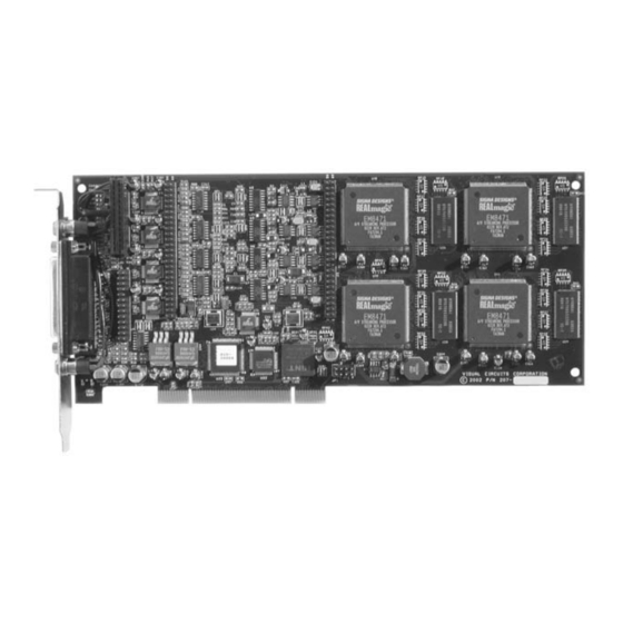
Overview Technical Description The Visual Circuits Harmony 2ES PCI MPEG decoder cards that support respectively, two or four independent outputs (channels) of high-quality video playback. These Harmony cards have their own unique driver and API structure designed to offer maximum compatibility with Visual Circuits ReelTime series cards. -
Page 11: Audio/Video Distribution
The output labeled “CH1/2” is designated for channels 1 & 2 and the output labeled “CH3/4” is designated for channels 3 & 4. Focus Enhancements does not carry cable adapters and accessories. See “AV Breakout Cables” on page 52. for details. Overview... -
Page 12: Application Interface (Api) For The Harmony 4Es
Overview Application Interface (API) for the Harmony 4ES The source code for the Harmony Vidserve demo program is provided for developers as an example of how to access the driver. The current version of the driver uses a proprietary C API interface (instead of a standard interface like MCI or Direct Show). -
Page 13: Installation Guide
The Visual Circuits Harmony 4ES decoder board is a 3/4 sized PCI card. The card is secured using an IO mounting bracket secured to the chassis. This bracket is affixed to the 25-pin female D-Sub output of the board. If a card is not seated securely in the PCI slot when the system power is applied, damage to the Harmony 4ES board may occur. -
Page 14: Card Installation
Installation Guide Card Installation To install the card, carefully slide the board into the selected PCI or PCIX slot of the main board. Ensure that the bracket is aligned with the IO opening of the chassis and that the outer edge of the card rests securely according to the chassis’... -
Page 15: Cable Installation (A/V Breakout)
Cable Installation (A/V Breakout) 1. Back the set-screws off fully before attaching the cable. Do not use the attaching screws to “pull” the cable onto the female D- Sub connector of the board. 2. Orient the D-Sub on the cable properly and apply slight even pressure while connecting the D-Subs. -
Page 16: Driver Installation For Windows 2000/2003/Nt 4.0/Xp
Installation Guide Driver Installation for Windows 2000/NT 4.0 and Windows 2003/XP 2000 2003 NT 4.0 Table 1: Installation Instructions Because the installation wizards for all operating systems are similar, the following installation instructions use the Windows 2000 Installation Wizard for the example. There are two parts to the installation process: Installation of Hardware (Part 1, on the following page) Running the Setup.exe application (Part 2, on page 16) - Page 17 Part 1: Installation Instructions (Hardware) Uninstall Earlier Versions of Visual Circuits Cards If you have previously installed a different type of Visual Circuits decoder card, or a different version for the Harmony decoder series, it is recommended that you uninstall that driver before proceeding.
- Page 18 Installation Guide 1. Install the decoder card(s) according to the board’s user manual. a. Power up the computer and log in to Windows. b. The Hardware Manager recognizes that new hardware is in the system and a message box appears stating that Windows has found new hardware.
- Page 19 3. When Windows asks for the location of the driver file for this device, select the location of the supplied driver disc and click Next Figure 6 Search For Driver Locations Screen 4. A dialog box appears, stating that this device does not have a digital signature and asks if the installation should continue: click Figure 7 Digital Signature Not Found Screen...
- Page 20 Installation Guide 5. Once Windows has installed the driver for the channel, select Finish Do Not Reboot System At This Time If at this time, the system asks if it should reboot, click NO. Continue to the next step and install the other channels and cards.
- Page 21 7. Because a Harmony driver is now installed on the system, select the second option, and then click Next Figure 9 Display List of Known Drivers Screen 8. The Harmony driver is now in the list and Hardware Wizard displays it under Models. Click Figure 10 Select a Device Driver Screen Display a list of the known drivers ...
- Page 22 Installation Guide 9. The wizard is ready to install the device driver. Click start the installation. Figure 11 Start Device Driver Installation Screen 10. A dialog box appears and states that the device does not have a digital signature and asks if the installation should continue: click Figure 12 Digital Signature Not Found Screen Next...
- Page 23 11. Again, once Windows has installed the driver for the channel, select Finish Do Not Reboot System At This Time If at this time, the system asks if it should reboot, click NO. Continue to the next step and install the other channels and cards.
- Page 24 Installation Guide 4. Choose the shortcut folder name to use. 5. Select Finish Start Menu Icons Once the system reboots, locate the following icons in the Visual Circuits group in the Start menu. The manuals require Acrobat Reader, 4.0 or higher. Harmony Driver User Manual Supplies detailed information on the driver parameters and hardware.
- Page 25 Installation Guide Sdk\Vidserve.zip: A Pkzipped file containing the Software Development Kit for the driver. This consists of the C source code to the Vidserve player program and all files needed to build it. Sdk\vb_api.zip: A Pkzipped file containing all files needed to create Visual Basic programs that use the driver.
-
Page 26: Starting Playback
Installation Guide Starting Playback Now that Harmony card is installed: 1. Verify that all software applications are closed. 2. Run Harmony Vidserve, the playback application located under Visual Circuits’ programs . Figure 13 Harmony Vidserve Playback Application Main Window 3. Browse for the MPEG file desired and open it. 4. -
Page 27: Installation Guide
Control Description Open Opens (loads) the MPEG file selected. > Plays or resumes play of a stopped file which has been opened (loaded). Stops a playing channel. File Displays the file and full path of the file to be played. You may type the file path or use Browse (see below). -
Page 28: Obtaining File Information
Installation Guide Obtaining File Information The Harmony supplies extensive information about the MPEG files the files currently playing through the File Information feature. To access this information, select main menu and then Figure 14 Harmony Vidserve Playback Application File Information Window Within the File Information window, the following information is available: Horizontal Size... -
Page 29: Using On Screen Displays
Using On Screen Displays The On Screen Display feature provides a ability to position an image, such as a company logo or graphic, on top of the video playback. To access the On Screen Display window, first select the drop down menu. Figure 15 Harmony Vidserve Playback Application On Screen Display Window The On Screen Display offers the capability of adjusting many of... -
Page 30: Testing Genlock And External Audio/Video
Installation Guide Testing Genlock and External Audio/Video The external audio/video feature allows the insertion of live external audio and/or video playback, such as a satellite or cable television broadcast, into the presentation mix. To test external audio/video and genlock, complete the following: 1. -
Page 31: Editing Driver Settings
DITING RIVER ETTINGS Driver Editing Utility: Harmony VccReg.exe Figure 16 Harmony VCCReg Parameter Editor Common Driver Parameters Harmony VccReg.exe is a driver editing utility designed specifically for editing the VCCmpeg2 driver settings. There are four tabs containing different parameters, descriptions of these parameters, and driver default settings. -
Page 32: General
Editing Driver Settings To change a parameter, enter the appropriate information in the Value field and click the set button restore the default value, click the set to default button General Network 0 = The driver cannot read files over the Windows NT network. -
Page 33: Performance
Performance BufferSizePerChannel Amount of RAM allocated for each channel. A larger buffer supports larger minimum file reads which reduces hard drive seeking. Default = 400000 hex, high performance playback (optimal) recommended. Range = 100000-800000 hex MaxDisks This parameter sets the number of disk read threads. - Page 34 Editing Driver Settings MinFileRead Sets the smallest file read size the driver will manage. The larger the minfileread is, the less HD seeking there will be. Setting minfileread to a quarter of BufferSizePerChannel (half MaxFileRead) is recommended. Default = 100000 hex Range = Fits evenly in BufferSizePerChannel...
- Page 35 NoCache 0 = Normal NT file system caching is used. 1 = The cache is not grown when files are played. Default = 0 Range = 0-1 NoREadBuffer Preferred Method for Dissolving File Caching NoReadBuff provides a preferable method to dissolve file caching and should be used instead of NoCache.
-
Page 36: Audio/Video
Editing Driver Settings Audio/Video DisableSync 0 = Enables audio/video synchronization. 1 = Disables audio/video synchronization. Default = 0 Range = 0-1 VideoTypes 0 = All channels output S-Video/Composite. 1 = All channels output Component. 2 = All channels output RGB (sync on green). -
Page 37: Special
Special InitOnOpen 0 = Files are loaded smoothly without a disturbance to the video output. 1 = The decoder chip is reinitialized whenever a new file is loaded. Output is black after load until it plays. Default = 0 Range = 0-1 Use mpgBlack for Black Screen, Not InitOnOpen If a black screen is required, use the call mpgBlack rather than this parameter. - Page 38 Editing Driver Settings MaxCards The number of channels to initialize can be fewer than the actual number of channels in the bus, for testing purposes. (There are four channels on each card). Default = 8 Range = 1-8 Multiapp 0 = Only one application can link to 4reelapi.dll at a time.
-
Page 39: Multi-Card Servers
ULTI ERVERS Multi-Threading and Drive Mapping Depending on hard drive speed and bitrate, proper drive mapping can be crucial for MPEG playback performance. This involves configuring the Harmony driver so that it reads from multiple physical hard drives simultaneously. In a system with two hard drives storing MPEG content, maximum performance occurs when data is read from both drives at the same time. - Page 40 Multi-Card Servers Multi-drive systems The use of multiple content drives in a system is useful when it is not possible to store all MPEG content on a single drive or there are multiple channels playing different content. Each channel group has its own drive(s) for content storage. For simplified mapping, divide the number of channels evenly and sequentially across multiple boards.
-
Page 41: Encoding Parameters
NCODING Listed below are requirements and recommendations for both Standard and High Definition encoding, that provide criteria to create MPEG files compatible with the Harmony playback system. 1. Files must be one of the following types: a. program stream MPEG2 or transport stream MPEG2 b. -
Page 42: Encoding Recommendations
Encoding Parameters Encoding Recommendations 1. Resolution: • 704 x 480 or 720 x 480 in NTSC • 704 x 576 or 720 x 576 in PAL 2. Closed GOP (Group of Pictures) with an “I-frame” every 15 frames is recommended. 3. - Page 43 6. Although the Harmony can transcode NTSC and PAL, it is recommended to encode to the video standard (NTSC or PAL) that the Harmony is set to display. 7. When encoding files, annotate and store notes on the audio levels of both the source tape and input settings of the encoder. This permits verifying the audio levels of later encoding sessions.
- Page 44 Encoding Parameters 11. To play back still images or computer-based graphics, hardware-based encoding systems are preferred. However, if a software encoder is needed, we recommend encoders such as DVMPEG (www.darvision.com).
-
Page 45: Cross-Channel Synchronization
The Harmony 2ES and 4ES provide the capability of cross-channel synchronization, i.e. the ability to coordinate the starting and stopping of video playback on multiple channels. The Harmony supports the following cross-channel synchronization features: Multiple synchronization groups The Harmony can support multiple synchronization groups. -
Page 46: Cross-Channel Sync Commands
Cross-Channel Synchronization Cross-channel Sync Commands The Harmony supports specific serial commands to implement cross-channel synchronization. mpgSyncChannel Use to create a synchronized group of channels. mpgUnSyncChannels Use to cancel a synchronization group. mpgPlaySyncChannels Use to start all channels in a group. mpgStopSyncChannels Use to stop all channels in a group. -
Page 47: Troubleshooting
Overview Only authorized technicians should perform board troubleshooting or system repairs. Unauthorized repair of systems may void warranty. Server Setup Check Prior to any troubleshooting, power down the system and verify that the card is properly installed in the system’s PCI or PCIX slot. Test only one card in the system at a time. -
Page 48: Getting Started
Troubleshooting Getting Started 1. Power the server up and open Harmony Vidserve playback application located under Visual Circuits programs. Figure 17 Main window of the Harmony Vidserve Playback Application On the main application window, the radio button selected should indicate Card 1 found. If it states “Harmony driver not found” see page 42 for tips on how to fix the error. -
Page 49: Troubleshooting Tips
Troubleshooting Tips BIOS Settings Ensure that the BIOS settings for Windows servers have the “Non PnP OS” selected. Blue screen If a Blue Screen occurs during Windows startup and Windows cannot be started, remove all Harmony cards from the system and reboot. Try a process of elimination to run the system in a single minimal system configuration, such as by inserting each device into the system and rebooting. -
Page 50: Harmony Driver Not Found!'' When Vidserve Started
Troubleshooting '' Harmony Driver not found!'' when Harmony Vidserve started Error Messages Displayed in Windows Event Viewer The error messages listed below are found in your system’s Event Viewer. For Windows NT: Locate Administrative Tools, then open Event Viewer. For Windows 2000: Right click on My Computer, then open Manage, then Event Viewer and finally System. -
Page 51: Stuttering Files During Playback
Circuits representative prior to encoding or designing your installation if there are any questions. Incorrect channel to drive mapping in multi-card systems with multiple content drives. For more information see Multi-Card Servers on page 31. Do Not Mix Harmony 2ES/4ES with Earlier Harmony or ReelTime Boards Troubleshooting... -
Page 52: Latent Images" Or "Flashing" During Playback
Troubleshooting "Latent Images" or "Flashing" during playback Incorrect source timecode provided or improperly closed encoding session. If the incorrect timecode for a file on tape is given, it is possible to encode a frame or two of trailer or header information from the tape. Often this “extra” frame may be seen only briefly and may appear as a visual flash on the screen during looping playback. -
Page 53: Overall Block Or Distorted Playback
Overall block or distorted playback Try playing another file or a Visual Circuits demo file to see if the problem is specific to a file. If so, the data may be corrupt. Make sure that NTSC is not being played to PAL or vice- versa (the vertical resolution is 576 in PAL and 480 in NTSC). -
Page 54: Harmony Vidserve Does Not Work At All
Troubleshooting Harmony Vidserve does not work at all Only one program can access the driver at a time. Close all programs using the Harmony driver and run Harmony Vidserve again. All channels pause when a new file is started on a channel Be sure buffers are fully loaded prior to playing. -
Page 55: Contacting Focus Enhancements
OCUS Support for Users If the Harmony decoder board is experiencing problems, first consult the Troubleshooting section on page 39 and the support information available at www.visualcircuits.com. Then, if more help is needed, please contact a Visual Circuits Value Added Reseller or Distributor. -
Page 56: Support For Vars And Distributors
Contacting Focus Enhancements Support for VARs and Distributors Value Added Resellers (VAR) and Distributors of Focus Enhancement’s Visual Circuits products, can call Focus Enhancement’s technical support. Calls are handled in the following manner: 1. A technical support representative records the information provided by the User: board serial number, date of purchase and seller, and problem description. -
Page 57: Vars And Distributors Returning Materials To Focus
Returning Materials to Focus Enhancements If the problems with the Harmony board can not be corrected over the telephone, it may be necessary to return the board to Focus Enhancements, Midwest Headquarters. All materials shipped back to Focus Enhancements must be accompanied by a Return Materials Authorization (RMA) number. - Page 58 Contacting Focus Enhancements...
-
Page 59: Appendix
PPENDIX This Appendix contains: AV Breakout Cables ......52 Harmony Specifications ......55 Vidcom Serial Command Interface. -
Page 60: Av Breakout Cables
Appendix AV Breakout Cables Feature Description Physical Length = 9.4'' (239mm) Height = 4.25'' (108mm) Connectors 25-pin D-Sub (use with universal breakout cable.) Dual 3.5 mm jacks for digital audio output. Power All active channels: • 10.5w Typical (playback to TV) PCI Voltages •... - Page 61 1 & 2 and the other for channels 3 & 4. Purchasing Cables Focus Enhancements does not stock or sell cables, cable components or cable building supplies. Please contact an Audio/ Video specialist for assistance...
-
Page 62: Pinouts
Appendix Pinouts Refer to the following chart for pin-out connections. Pin No. Table 5 Pin-Out Connections Harmony GROUND AUDIO L/3 COMP 3 / BLUE 3 LUMA 3 / GREEN 3 AUDIO L/2 COMP 2 / BLUE 2 LUMA 2 / GREEN 2 AUDIO L/1 COMP 1 / BLUE 1 LUMA 1 / GREEN 1... -
Page 63: Specifications
Specifications Feature Description Physical Length = 9.4'' (239mm) Height = 4.25'' (108mm) Connectors 25-pin D-Sub (use with universal breakout cable.) Dual 3.5 mm jacks for digital audio output. Power All active channels: • 10.5w Typical (playback to TV) PCI Voltages •... - Page 64 Appendix Feature Description Video Output level composite video: 1 volt peak-to-peak when terminated with 75ohms Parameters Output level RGB (RT+): .7v peak-to-peak when terminated with 75 ohms Standards: NTSC or PAL software selectable Encoder:Broadcast quality digital video encoder with post filtering Resolution:CCIR 601 720x480 NTSC or 704 x 576 PAL Driver supports automatic selection of SIF format for...
-
Page 65: Vidcom Serial Command Interface
Vidcom Serial Command Interface The Visual Circuits Vidcom application provides a serial command interface for editing and sending commands via a direct connection to the server. Connecting directly to the Server Use a null modem cable (RS232, female DB-9 to female DB-9) to connect to the server serial COM port from a laptop or PC. -
Page 66: Vidcom Supported Serial Commands
Appendix Vidcom Supported Serial Commands File Playback Commands Audio / Video Output Commands Table 7 Serial Commands Supported by Vidcom mpgLoad mpgLoadNext mpgPlay mpgPlayAll mpgStop mpgStopAll mpgAutoRepeat mpgNoRepeat mpgSeek mpgSetAudioPID mpgSetVideoPID mpgClose mpgSetInitOnOpen mpgMute mpgUnMute mpgBlack mpgUnBlack mpgColorBarOn mpgColorBarOff genSetAudio genSetVideo mpgSetVolumeLeftRight... - Page 67 Onscreen Display Commands Cross-channel Synchronization Commands (after driver V3.12.5) Table 7 Serial Commands Supported by Vidcom (continued) For a complete description of for these commands and all serial commands supported by the Harmony, refer to the Harmony SDK. osdLoadGIF (calls osdLoadBMP) osdSetXYMix osdShow osdHide...
- Page 68 Appendix...
-
Page 69: Index
audio bit rate, SD cables 3, 7 digital Dolby Digital stream test tones audio level, base line auto loop auto play AuxSkip BIOS bit rate audio, SD encoding sampling, SD encoding black browse buffers BufferSizePerChannel interface card installation 5, 6 chassis clock speed close all... - Page 70 Index cache, dissolving information information, Vidserve flashing images 19, 22 genlock GOP (Group of Pictures) hardware 52, 55 specifications information MPEG files playing InitOnOpen installing interface 11172 (MPEG-1) 13818 (MPEG-2) latent images mapping drives 25, 31 MaxDisks drive parameter multiple drives single drive MaxDMA MaxFileRead...
- Page 71 playback Vidserve playlist, looping file length position presentation time stamp program stream end code recommendations encoding, SD resolution return materials authorization RS232 sampling bit rate SD encoding, recommended serial commands Vidcom server maximum number cards maximum number channels servers multi-card set-screws show stats 35, 44...
- Page 74 813-0048b © 2005 Focus Enhancements...
Need help?
Do you have a question about the Harmony 2ES and is the answer not in the manual?
Questions and answers