Table of Contents
Advertisement
Quick Links
SPLIT-TYPE, HEAT PUMP AIR CONDITIONERS
TECHNICAL & SERVICE MANUAL
Series PMFY
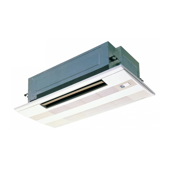
Indoor unit
[Model names] [Service Ref.]
PMFY-P20VBM-E
PMFY-P20VBM-E
PMFY-P20VBM-E#2
PMFY-P20VBM-ER4
PMFY-P25VBM-E
PMFY-P25VBM-E
PMFY-P25VBM-E#2
PMFY-P25VBM-ER4
PMFY-P32VBM-E
PMFY-P32VBM-E
PMFY-P32VBM-E#2
PMFY-P32VBM-ER4
PMFY-P40VBM-E
PMFY-P40VBM-E
PMFY-P40VBM-E#2
PMFY-P40VBM-ER4
INDOOR UNIT
Ceiling Cassettes
R410A
PMFY-P20VBM-E
PMFY-P20VBM-ER3
PMFY-P25VBM-E
PMFY-P25VBM-ER3
PMFY-P32VBM-E
PMFY-P32VBM-ER3
PMFY-P40VBM-E
PMFY-P40VBM-ER3
CONTENTS
1. TECHNICAL CHANGES ..................... 2
2. SAFETY PRECAUTION ..................... 3
3. PART NAMES AND FUNCTIONS ...... 5
4. SPECIFICATIONS ............................ 12
5. OUTLINES AND DIMENSIONS ....... 16
6. WIRING DIAGRAM ........................... 17
7. REFRIGERANT SYSTEM DIAGRAM .... 21
8. TROUBLESHOOTING ...................... 22
9. DISASSEMBLY PROCEDURE ......... 32
10. SERVICE PARTS LIST ..................... 36
March 2019
No. OC307
REVISED EDITION-F
Revision:
• Some descriptions have
1
been modified in REVISED
EDITION-F.
OC307 REVISED
EDITION-E is void.
1
1
1
Advertisement
Table of Contents

Related Manuals for Mitsubishi Electric City Multi PMFY Series


Summary of Contents for Mitsubishi Electric City Multi PMFY Series
- Page 1 SPLIT-TYPE, HEAT PUMP AIR CONDITIONERS March 2019 No. OC307 REVISED EDITION-F TECHNICAL & SERVICE MANUAL Ceiling Cassettes Series PMFY R410A Indoor unit Revision: [Model names] [Service Ref.] • Some descriptions have PMFY-P20VBM-E PMFY-P20VBM-E PMFY-P20VBM-E been modified in REVISED EDITION-F. PMFY-P20VBM-E#2 PMFY-P20VBM-ER3 OC307 REVISED PMFY-P20VBM-ER4...
- Page 2 TECHNICAL CHANGES PMFY-P20VBM-ER3 PMFY-P20VBM-ER4 PMFY-P25VBM-ER3 PMFY-P25VBM-ER4 PMFY-P32VBM-ER3 PMFY-P32VBM-ER4 PMFY-P40VBM-ER3 PMFY-P40VBM-ER4 1. INDOOR CONTROLLER BOARD has been changed. (S/W version up) PMFY-P20VBM-E#2 PMFY-P20VBM-ER3 PMFY-P25VBM-E#2 PMFY-P25VBM-ER3 PMFY-P32VBM-E#2 PMFY-P32VBM-ER3 PMFY-P40VBM-E#2 PMFY-P40VBM-ER3 1. DRAIN PIPE has been changed. 2. JOINT SOCKET (FOR DRAIN PIPE) has been added. PMFY-P20VBM-E PMFY-P20VBM-E#2 PMFY-P25VBM-E...
- Page 3 SAFETY PRECAUTION Cautions for units utilizing refrigerant R410A Use a vacuum pump with a reverse flow check Use new refrigerant pipes. valve. In case of using the existing pipes for R22, be careful with Vacuum pump oil may flow back into refrigerant cycle and the followings.
- Page 4 [1] Cautions for service (1) Perform service after recovering the refrigerant left in unit completely. (2) Do not release refrigerant in the air. (3) After completing service, charge the cycle with specified amount of refrigerant. (4) When performing service, install a filter drier simultaneously. Be sure to use a filter drier for new refrigerant.
- Page 5 PART NAMES AND FUNCTIONS 3-1. Indoor Unit Auto Air Swing Vane Guide vane Disperses airflow up and Air flow can be changed to horizontal down and adjusts the angle by moving the Guide vane to the left or right. of airflow direction. Horizontal Air Outlet Filters Air intake...
- Page 6 3-2. WIRED REMOTE CONTROLLER <PAR-30MAA/PAR-31MAA> Wired remote controller function * The functions which can be used are restricted according to the model. : Supported : Unsupported PAR-30MAA/PAR-31MAA Function PAR-21MAA Slim CITY MULTI Body Product size H × W × D (mm) 120 ×...
- Page 7 Room Set temp. Cool Auto Mode Temp. The main display can be displayed in two different modes: "Full" and "Basic". The factory setting is "Full". To switch to the "Basic" mode, change the setting on the Main display setting. <Full mode> <Basic mode>...
- Page 8 Menu structure Press the button. MENU Main menu Move the cursor to the desired item with the buttons, and press the button. SELECT Vane · Louver · Vent. (Lossnay) High power Timer On / Off timer Auto-Off timer Filter information Error information Weekly timer Energy saving...
- Page 9 Main menu list Setting and display items Setting details Vane · Louver · Vent. Use to set the vane angle. • Select a desired vane setting from five different settings. (Lossnay) Use to turn ON / OFF the louver. • Select a desired setting from "ON" and "OFF." Use to set the amount of ventilation.
- Page 10 Setting and display items Setting details Initial setting Display Make the settings for the remote controller related items as necessary. details Clock: The factory settings are "Yes" and "24h" format. Temperature: Set either Celsius (°C) or Fahrenheit (°F). Room temp. : Set Show or Hide. Auto mode: Set the Auto mode display or Only Auto display.
- Page 11 3-3. WIRED REMOTE CONTROLLER <PAR-21MAA> “Sensor” indication Display Section Displayed when the remote controller sensor is used. Day-of-Week For purposes of this explanation, Shows the current day of the week. all parts of the display are shown. During actual operation, only the Time/Timer Display relevant items will be lit.
- Page 12 SPECIFICATIONS 4-1. SPECIFICATION PMFY-P20VBM-E PMFY-P32VBM-E PMFY-P40VBM-E PMFY-P25VBM-E PMFY-P32VBM-E PMFY-P40VBM-E PMFY-P20VBM-E PMFY-P25VBM-E Item PMFY-P32VBM-E#2 PMFY-P40VBM-E#2 PMFY-P20VBM-E#2 PMFY-P25VBM-E#2 PMFY-P20VBM-ER3 PMFY-P32VBM-ER3 PMFY-P40VBM-ER3 PMFY-P25VBM-ER3 PMFY-P20VBM-ER4 PMFY-P32VBM-ER4 PMFY-P40VBM-ER4 PMFY-P25VBM-ER4 · Single phase 220V-230V-240V 50Hz / 220V 60Hz Power Cooling capacity Heating capacity Cooling 0.042 0.044 0.044 0.054 Input...
- Page 13 4-2. ELECTRIC PARTS SPECIFICATIONS PMFY-P20VBM-E PMFY-P25VBM-E PMFY-P32VBM-E PMFY-P40VBM-E Service ref. PMFY-P20VBM-E PMFY-P25VBM-E PMFY-P32VBM-E PMFY-P40VBM-E PMFY-P20VBM-E#2 PMFY-P25VBM-E#2 PMFY-P32VBM-E#2 PMFY-P40VBM-E#2 Symbol PMFY-P20VBM-ER3 PMFY-P25VBM-ER3 PMFY-P32VBM-ER3 PMFY-P40VBM-ER3 PMFY-P20VBM-ER4 PMFY-P25VBM-ER4 PMFY-P32VBM-ER4 PMFY-P40VBM-ER4 Parts name Room temperature TH21 Resistance 0:/15k", 10:/9.6k", 20:/6.3k", 25:/5.4k", 30:/4.3k", 40:/3.0k" thermistor Liquid pipe thermistor TH22 Resistance 0:/15k", 10:/9.6k", 20:/6.3k", 25:/5.4k", 30:/4.3k", 40:/3.0k"...
- Page 14 4-3. AIR CAPACITY TAKEN FROM OUTSIDE PMFY-P·VBM-E series enables to take fresh air from outside. When taking fresh air, the duct fan is used. The air capacity should be 20% or less of the air flow SPEC(Hi). 288.5 Unit : mm 4-{2.8 Fresh air intake hole Fresh air intake hole...
- Page 15 4-4. NOISE CRITERION CURVES PMFY-P25/32VBM-E PMFY-P20VBM-E NOTCH SPL(dB) LINE PMFY-P25/32VBM-E NOTCH SPL(dB) LINE PMFY-P20VBM-E High High PMFY-P25/32VBM-E#2 PMFY-P20VBM-E#2 Medium1 Medium1 Medium2 PMFY-P25/32VBM-ER3 Medium2 PMFY-P20VBM-ER3 PMFY-P25/32VBM-ER4 PMFY-P20VBM-ER4 NC-70 NC-70 NC-60 NC-60 NC-50 NC-50 NC-40 NC-40 NC-30 NC-30 APPROXIMATE THRESHOLD OF HEARING FOR NC-20 NC-20 CONTINUOUS...
-
Page 16: Table Of Contents
OUTLINES AND DIMENSIONS PMFY-P20VBM-E PMFY-P25VBM-E PMFY-P32VBM-E PMFY-P40VBM-E PMFY-P20VBM-E PMFY-P25VBM-E PMFY-P32VBM-E PMFY-P40VBM-E PMFY-P20VBM-E#2 PMFY-P25VBM-E#2 PMFY-P32VBM-E#2 PMFY-P40VBM-E#2 PMFY-P20VBM-ER3 PMFY-P25VBM-ER3 PMFY-P32VBM-ER3 PMFY-P40VBM-ER3 PMFY-P20VBM-ER4 PMFY-P25VBM-ER4 PMFY-P32VBM-ER4 PMFY-P40VBM-ER4 Unit : mm OC307F... -
Page 17: Pmfy-P20Vbm-E
WIRING DIAGRAM PMFY-P20VBM-E PMFY-P25VBM-E PMFY-P32VBM-E PMFY-P40VBM-E FUSE BREAKER PULL BOX (15A) (15A) POWER SUPPLY TO OUTDOOR UNIT TO NEXT ~/N 220-230-240V 50Hz BC CONTROLLER INDOOR UNIT 220V 60Hz REMOTE CONTROLLER DC24-30V TB2 L M1 M2 (SHIELD) TO MA-REMOTE CONTROLLER DC8.7-13V TB15 CN3A CN2M... -
Page 18: Pmfy-P20Vbm-E
PMFY-P20VBM-E PMFY-P25VBM-E PMFY-P32VBM-E PMFY-P40VBM-E FUSE BREAKER TO OUTDOOR UNIT PULL BOX (15A) (15A) BC CONTROLLER POWER SUPPLY TO NEXT REMOTE CONTROLLER ~ / N INDOOR UNIT DC24-30V 220-240V 50Hz 220V 60Hz TO MA-REMOTE CONTROLLER DC8.7-13V M1 M2 S (SHIELD) TB15 CN3A (BLU) REMOCON... -
Page 19: Pmfy-P20Vbm-E#2 Pmfy-P20Vbm-Er3
PMFY-P20VBM-E#2 PMFY-P25VBM-E#2 PMFY-P32VBM-E#2 PMFY-P40VBM-E#2 PMFY-P20VBM-ER3 PMFY-P25VBM-ER3 PMFY-P32VBM-ER3 PMFY-P40VBM-ER3 TO OUTDOOR UNIT TO MA-REMOTE BC CONTROLLER CONTROLLER REMOTE CONTROLLER DC8.7-13V DC24-30V FUSE BREAKER PULL BOX POWER SUPPLY TO NEXT INDOOR 220-240V 50Hz UNIT 220V 60Hz TB15 M1 M2 (SHIELD) FUSE DC311 ZNR01 339V D.U.M... -
Page 20: Pmfy-P20Vbm-Er4
PMFY-P20VBM-ER4 PMFY-P25VBM-ER4 PMFY-P32VBM-ER4 PMFY-P40VBM-ER4 TO OUTDOOR UNIT TO MA-REMOTE BC CONTROLLER CONTROLLER REMOTE CONTROLLER DC8.7-13V DC24-30V FUSE BREAKER PULL BOX (15A) (15A) POWER SUPPLY TO NEXT ~ / N INDOOR 220-240V 50Hz UNIT 220V 60Hz TB15 M1 M2 (SHIELD) CND (BLK) FUSE (YLW) D.U.M... -
Page 21: Unit: Mm
REFRIGERANT SYSTEM DIAGRAM PMFY-P20VBM-E PMFY-P25VBM-E PMFY-P32VBM-E PMFY-P40VBM-E PMFY-P20VBM-E PMFY-P25VBM-E PMFY-P32VBM-E PMFY-P40VBM-E PMFY-P20VBM-E#2 PMFY-P25VBM-E#2 PMFY-P32VBM-E#2 PMFY-P40VBM-E#2 PMFY-P20VBM-ER3 PMFY-P25VBM-ER3 PMFY-P32VBM-ER3 PMFY-P40VBM-ER3 PMFY-P20VBM-ER4 PMFY-P25VBM-ER4 PMFY-P32VBM-ER4 PMFY-P40VBM-ER4 Gas pipe Strainer (#50mesh) temperature thermistor TH23 Gas pipe Liquid pipe temperature thermistor TH22 Flare connection Liquid pipe Heat exchanger Linear expansion valve Strainer (#100mesh) -
Page 22: Pmfy-P25Vbm-Epmfy-P25Vbm-E
TROUBLESHOOTING 8-1. HOW TO CHECK THE PARTS PMFY-P20VBM-E PMFY-P25VBM-E PMFY-P32VBM-E PMFY-P40VBM-E PMFY-P20VBM-E PMFY-P25VBM-E PMFY-P32VBM-E PMFY-P40VBM-E PMFY-P20VBM-E#2 PMFY-P25VBM-E#2 PMFY-P32VBM-E#2 PMFY-P40VBM-E#2 PMFY-P20VBM-ER3 PMFY-P25VBM-ER3 PMFY-P32VBM-ER3 PMFY-P40VBM-ER3 PMFY-P20VBM-ER4 PMFY-P25VBM-ER4 PMFY-P32VBM-ER4 PMFY-P40VBM-ER4 Parts name Check points Room temperature Disconnect the connector then measure the resistance with a tester. thermistor (TH21) (At the ambient temperature 10: - 30:) - Page 23 <Thermistor Characteristic graph> < Thermistor for lower temperature > Room temperature thermistor (TH21) Thermistor for Liquid pipe temperature thermistor (TH22) lower temperature Gas pipe temperature thermistor (TH23) Thermistor R =15k' ± 3% Fixed number of B=3480 ± 2% Rt=15exp { 3480( 273+t 0: : 15k'...
- Page 24 <Output pulse signal and the valve operation> Output Output (Phase) Closing a valve : 1 → 2 → 3 → 4 → 1 Opening a valve : 4 → 3 → 2 → 1 → 4 The output pulse shifts in above order. •...
- Page 25 8-2. TROUBLESHOOTING Check method of indoor fan motor (fan motor / controller board) Notes · High voltage is applied to the connecter (FAN)(CNMF1, 2) for the fan motor. Pay attention to the service. · Do not pull out the connector (FAN)(CNMF1, 2) for the motor with the power supply on, doing so may result in damage to the board.
-
Page 26: Pmfy-P32Vbm-Epmfy-P32Vbm-Epmfy-P32Vbm-E#2 Pmfy-P32Vbm-Er3
8-3. FUNCTION OF DIP SWITCH PMFY-P20VBM-E PMFY-P25VBM-E PMFY-P32VBM-E PMFY-P40VBM-E PMFY-P20VBM-E PMFY-P25VBM-E PMFY-P32VBM-E PMFY-P40VBM-E PMFY-P20VBM-E#2 PMFY-P25VBM-E#2 PMFY-P32VBM-E#2 PMFY-P40VBM-E#2 PMFY-P20VBM-ER3 PMFY-P25VBM-ER3 PMFY-P32VBM-ER3 PMFY-P40VBM-ER3 PMFY-P20VBM-ER4 PMFY-P25VBM-ER4 PMFY-P32VBM-ER4 PMFY-P40VBM-ER4 The black square ( ) indicates a switch position. Operation by switch Effective Switch Pole Function Remarks timing... - Page 27 The black square ( ) indicates a switch position. Effective Switch Pole Operation by switch Remarks timing Address board SW11 1s digit How to set addresses SW12 SW11 address Example : If address is “3”, remain SW12 setting <Initial setting> (for over 10) at “0”, and match SW11 (for 1 to 9) SW12 SW12...
- Page 28 8-4. TEST POINT DIAGRAM 8-4-1. Indoor controller board PMFY-P20VBM-E PMFY-P25VBM-E PMFY-P32VBM-E PMFY-P40VBM-E PMFY-P20VBM-E PMFY-P25VBM-E PMFY-P32VBM-E PMFY-P40VBM-E CN32 Capacity setting Mode selection Model selection Connector (Remote switch) CN27 Damper CN25 Humidifier CN6V Drain pump Vane motor output output (DP) (MV) Between 1 to 3 CN52 220-240V AC Remote indicator...
- Page 29 Indoor controller board PMFY-P20VBM-E#2 PMFY-P25VBM-E#2 PMFY-P32VBM-E#2 PMFY-P40VBM-E#2 PMFY-P20VBM-ER3 PMFY-P25VBM-ER3 PMFY-P32VBM-ER3 PMFY-P40VBM-ER3 PMFY-P20VBM-ER4 PMFY-P25VBM-ER4 PMFY-P32VBM-ER4 PMFY-P40VBM-ER4 Power supply Drain pump output (DP) 1-3 : 220-240V AC 1-3 : 220-240V AC FUSE 6.3A 250V CNMF1, CNMF2 FAN motor CNMF11-CNMF21 : 310-340V DC CNMF27-1 : 0-15V DC LED1 Main power supply...
- Page 30 Indoor controller board PMFY-P20VBM-E#2 PMFY-P25VBM-E#2 PMFY-P32VBM-E#2 PMFY-P40VBM-E#2 PMFY-P20VBM-ER3 PMFY-P25VBM-ER3 PMFY-P32VBM-ER3 PMFY-P40VBM-ER3 PMFY-P20VBM-ER4 PMFY-P25VBM-ER4 PMFY-P32VBM-ER4 PMFY-P40VBM-ER4 FUSE 6.3A 250V Power supply Drain pump output (DP) 1-3 : 220-240V AC 1-3 : 220-240V AC CNMF1, CNMF2 FAN motor CNMF11-CNMF21 : 310-340V DC CNMF27-1 : 0-15V DC LED1 Main power supply...
- Page 31 8-4-2. Address board PMFY-P20VBM-E PMFY-P25VBM-E PMFY-P32VBM-E PMFY-P40VBM-E PMFY-P20VBM-E PMFY-P25VBM-E PMFY-P32VBM-E PMFY-P40VBM-E PMFY-P20VBM-E#2 PMFY-P25VBM-E#2 PMFY-P32VBM-E#2 PMFY-P40VBM-E#2 PMFY-P20VBM-ER3 PMFY-P25VBM-ER3 PMFY-P32VBM-ER3 PMFY-P40VBM-ER3 PMFY-P20VBM-ER4 PMFY-P25VBM-ER4 PMFY-P32VBM-ER4 PMFY-P40VBM-ER4 Voltage selector Function setting SW12 SW11 SW14 Address setting Address setting Branch No. 10ths DIGIT 1s DIGIT OC307F...
- Page 32 DISASSEMBLY PROCEDURE PMFY-P20VBM-E PMFY-P25VBM-E PMFY-P32VBM-E PMFY-P40VBM-E PMFY-P20VBM-E PMFY-P25VBM-E PMFY-P32VBM-E PMFY-P40VBM-E PMFY-P20VBM-E#2 PMFY-P25VBM-E#2 PMFY-P32VBM-E#2 PMFY-P40VBM-E#2 PMFY-P20VBM-ER3 PMFY-P25VBM-ER3 PMFY-P32VBM-ER3 PMFY-P40VBM-ER3 PMFY-P20VBM-ER4 PMFY-P25VBM-ER4 PMFY-P32VBM-ER4 PMFY-P40VBM-ER4 Be careful when removing heavy parts. OPERATING PROCEDURE PHOTOS/FIGURES Photo 1 Air intake grille 1. Removing the grille Opening the air intake grille Air outlet (1) Press the...
- Page 33 OPERATING PROCEDURE PHOTOS/FIGURES Figure 6 Hooks Removing the grille (1) Open the intake grille by pressing of the air intake PUSH grille and remove the air filter (× 2). (See Figure 1) (2) Remove the screw cover in the middle of the air outlet. (See Figure 7) (3) Open the upper and lower flaps on the indoor unit com- pletely.
- Page 34 OPERATING PROCEDURE PHOTOS/FIGURES Photo 2 2. Removing the electrical parts box Claw in middle Nozzle Electrical parts of nozzle (1) Remove the grille. (2) Remove the address board cover. (3) Remove the electrical parts cover. (4) Disconnect the connectors of fan motor, vane motor, drain pump, room temperature thermistor, pipe temperature thermistor (Liquid, Gas),...
- Page 35 OPERATING PROCEDURE PHOTOS/FIGURES Photo 6 Drain sensor Drain pump 5. Removing the drain pump (1) Remove the grille. (2) Unhook the claw in the middle of nozzle and remove the drain pan. (See Photo 2) (3) Remove the address board cover. (See Photo 3) (4) Remove the electrical parts cover.
- Page 36 SERVICE PARTS LIST PANEL PARTS PMP-40BM (FOR PMFY-P20/25/32/40VBM-E PMP-40BMW (FOR PMFY-P20/25/32/40VBM-E#2, PMFY-P20/25/32/40VBM-ER3, PMFY-P20/25/32/40VBM-ER4) Q'ty/set 7MB001-P01_01.ai Wiring Recommended Remarks Specification Part No. Part Name Diagram PMP- PMP- (Drawing No.) Q'ty Symbol 40BMW 40BM T7W E16 003 AIR OUTLET GRILLE T7W E22 003 AIR OUTLET GRILLE R 0 1 E 0 1 0 5 5 LATCH...
- Page 37 ELECTRICAL PARTS PMFY-P20VBM-E PMFY-P25VBM-E PMFY-P32VBM-E PMFY-P40VBM-E PMFY-P20VBM-E PMFY-P25VBM-E PMFY-P32VBM-E PMFY-P40VBM-E PMFY-P20VBM-E#2 PMFY-P25VBM-E#2 PMFY-P32VBM-E#2 PMFY-P40VBM-E#2 PMFY-P20VBM-ER3 PMFY-P25VBM-ER3 PMFY-P32VBM-ER3 PMFY-P40VBM-ER3 PMFY-P20VBM-ER4 PMFY-P25VBM-ER4 PMFY-P32VBM-ER4 PMFY-P40VBM-ER4 Q'ty/set Wiring Remarks Specification Part No. Part Name PMFY-P20/25/32/40 Diagram (Drawing No.) Symbol VBM-E VBM-E VBM-E#2 VBM-ER3 VBM-ER4 —...
- Page 38 FUNCTIONAL PARTS PMFY-P20VBM-E PMFY-P20VBM-ER3 PMFY-P25VBM-E PMFY-P25VBM-ER3 PMFY-P32VBM-E PMFY-P32VBM-ER3 PMFY-P40VBM-E PMFY-P40VBM-ER3 PMFY-P20VBM-E PMFY-P20VBM-ER4 PMFY-P25VBM-E PMFY-P25VBM-ER4 PMFY-P32VBM-E PMFY-P32VBM-ER4 PMFY-P40VBM-E PMFY-P40VBM-ER4 PMFY-P20VBM-E#2 PMFY-P25VBM-E#2 PMFY-P32VBM-E#2 PMFY-P40VBM-E#2 28, 29 23, 24 7MB001-A01_02 OC307F...
- Page 39 Q'ty/set Wiring PMFY-P Remarks Specification Part No. Part Name Diagram (Drawing No.) VBM-E VBM-E VBM-E#2 VBM-ER3 VBM-ER4 Symbol 20,25 32,40 20,25 32,40 20,25 32,40 20,25 32,40 20,25 32,40 R01 E13 097 WASHERS SET R01 E05 660 PIPE COVERS SET R01 18J 523 JOINT SOCKET —...
- Page 40 HEAD OFFICE : TOKYO BUILDING., 2-7-3, MARUNOUCHI, CHIYODA-KU, TOKYO100-8310, JAPAN cCopyright 2004 MITSUBISHI ELECTRIC CORPORATION Issued: Mar. 2019 No. OC307 REVISED EDITION-F Issued: Dec. 2012 No. OC307 REVISED EDITION-E Issued: Oct. 2009 No. OC307 REVISED EDITION-D PDF 7 Issued: Sep. 2008 No. OC307 REVISED EDITION-C PDF 7 Issued: Jul.
Need help?
Do you have a question about the City Multi PMFY Series and is the answer not in the manual?
Questions and answers