Table of Contents
Advertisement
Quick Links
To understand this product, and for safety and
optimum performance, read this manual before
starting the engine. Pay special attention to
SAFETY INSTRUCTIONS highlighted by this
symbol.
MODEL NO. 03550—
MODEL NO. 03551—
®
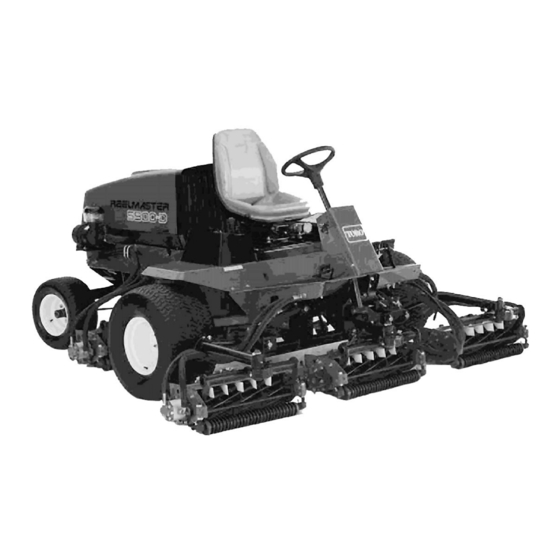
REELMASTER
©The TORO COMPANY—2000
FORM NO. 3325-160 Rev B
200000001
& UP
200000001
& UP
®
It means CAUTION, WARNING or DANGER—
personal safety instruction. Failure to comply with
the instruction may result in personal injury.
OPERATOR'S
MANUAL
5500-D
Advertisement
Table of Contents

Subscribe to Our Youtube Channel
Related Manuals for Toro REELMASTER 5500-D

Summary of Contents for Toro REELMASTER 5500-D
- Page 1 It means CAUTION, WARNING or DANGER— optimum performance, read this manual before personal safety instruction. Failure to comply with starting the engine. Pay special attention to the instruction may result in personal injury. SAFETY INSTRUCTIONS highlighted by this symbol. ©The TORO COMPANY—2000...
-
Page 2: Table Of Contents
This operator's manual has instructions on safety, operation, and maintenance. This manual emphasizes safety, mechanical and general product information. DANGER, WARNING and CAUTION identify safety messages. Whenever the triangular safety alert symbol appears, understand the safety message that follows. “IMPORTANT” highlights special mechanical information and “NOTE” emphasizes general product information worthy of special attention. -
Page 3: Safety
Safety Thoroughly inspect the area where the Training equipment is to be used and remove all objects Read the instructions carefully. Be familiar which may be thrown by the machine. with the controls and the proper use of the equipment. WARNING—Petrol is highly flammable. - Page 4 Safety • engage the clutch slowly, and always keep • stop the engine and remove the key. the machine in gear, especially when travailing downhill; 13. Disengage the drive to attachments when transporting or not in use. • machine speeds should be kept low on slopes and during tight turns;...
- Page 5 Safety done outdoors. Sound & Vibration Levels 8. Be careful during adjustment of the machine to SOUND PRESSURE LEVEL prevent entrapment of the fingers between moving blades and fixed parts of the machine. This unit has an equivalent continuous A-weighted sound pressure at the operator ear of: 88 dB(A), 9.
-
Page 6: Symbol Glossary
Symbol Glossary Caustic liquids, Poisonous Electrical shock, High pressure High pressure High pressure Crushing of Crushing of chemical burns to fumes or toxic electrocution fluid, injection spray, erosion of spray, erosion of fingers or hand, toes or foot, force fingers or hand gases, asphyxiation into body flesh... - Page 7 Safety Eye protection Head protection Hearing Caution, toxic First aid Flush with water Engine Transmission must be worn must be worn protection must risk be worn Fire, open light Hydraulic Brake system Coolant (water) Intake air Exhaust gas Pressure & smoking system prohibited Level...
- Page 8 Safety Engine coolant Engine coolant f Engine Engine intake/ Engine intake/ Engine intake/ Engine start Engine stop pressure ilter lubricating oil combustion air combustion air air filter pressure pressure n/min Engine failure/ Engine rotational Choke Primer (start aid) Electrical preheat Transmission oil Transmission oil Transmission oil malfunction...
-
Page 9: Specifications
Specifications Engine: Kubota three-cylinder, 4-cycle, liquid- front traction wheels. Brakes are controlled by cooled diesel. 26kW (35 hp) @ governed to 3200 individual pedals operated by the left foot. rpm; 1123 cc displacement. Heavy-duty, 3-stage, Hydrostatic braking through the traction drive. remote-mounted air cleaner. - Page 10 Safety Recommended Height-of-Cut: 5-Blade Cutting Unit: 2.54–4.5cm (1.00–1.75 in.) 7-Blade Cutting Unit: 1.27–2.54 cm (0.5–1.0 in.) 11-Blade Cutting Unit 0.95–1.9 cm (0.375–0.75 in.) Weight: Model 03550 1,105 kg (2,962 lbs.)* Model 03551 1,198 kg (3,210 lbs.)* *With 7-Blade Cutting Units, baskets & full fluid levels Optional Equipment: 5-Blade Cutting Unit (7 in.)
-
Page 11: Before Operating
Before Operating Check the Engine Oil CAUTION Park the machine on a level surface, stop the If the engine has been running, pressurized hot engine and remove the key from the ignition coolant can escape when the radiator cap is switch. -
Page 12: Check The Transmission Fluid
15–22 l of hydraulic oil. Order Part system. The transmission and axle housing are No. 44-2500 from your authorized Toro distributor. shipped from the factory with 4.7 l (5 quarts) of Mobil 424 hydraulic fluid. However, check the ➀... - Page 13 Before Operating Amoco Amoco 1000 temperatures may result in decreased efficiency in International Harvester Hy-Tran some hydraulic components compared to using the Texaco Mobil DTE 26 type oils. Shell Donax TD Union Oil Hydraulic/Tractor Fluid The Mobil DTE 26 type oils are straight viscosity Chevron Tractor Hydraulic Fluid oils which remain slightly more viscous at higher...
-
Page 14: Check Rear Axle Lubricant (Model 03551 Only)
Before Operating the mark on the dipstick. If the level is low, add fluid to raise the level to the full mark. Install the dipstick and cap onto the filler neck. Check Rear Axle Lubricant (Model 03551 only) Figure 7 1. -
Page 15: Controls
Controls Seat (Fig. 8)—The seat adjusting lever allows 10 Traction Speed Limiter (Fig .9)—Preset this lever to limit the amount the traction pedal can be cm (4 inches) fore and aft adjustment. The seat depressed in the forward direction to maintain a adjusting knob adjusts the seat for operators’... - Page 16 Controls Figure 10 Figure 11 1. Lower mow/raise control lever 1. Reel speed controls 2. Speedometer 2. Backlap knobs 3. Fuel gauge 4. Engine coolant temperature gauge 5. Engine oil pressure warning light 6. Engine coolant temperature warning light. Reel speed Controls (Fig. 11)—Control rpm of the 7.
-
Page 17: Operation
Operation Bleeding the Fuel System CAUTION Raise the hood. Before servicing or making adjustments to the machine, stop the engine and remove the key from Loosen the air bleed screw on top of the fuel the switch. filter/water separator (Fig. 12) Starting and Stopping IMPORTANT: The fuel system must be bled in the following situations. -
Page 18: Setting Reel Speed
Operation Figure 14 1. Fuel injection pump bleed screw Pump the lever on the fuel pump (Fig. 12) until a solid stream of fuel flows out around the screw on the fuel injection pump. Tighten the air bleed screw. Note: Normally the engine should start after the above bleeding procedures. -
Page 19: Adjusting Rear Lift Arm Counterbalance
Operation differences in grass condition, grass length removed, and personal preference of the superintendent. For a cut with more grass removed but slightly more clip visibility, move the reel speed selector knobs one position lower than specified. For a cut with less grass removed and slightly less clip visibility, move the reel speed selector knobs one position higher than specified. -
Page 20: Diagnostic Light
Operation Attach a suitable chain, strap or cable to the center of the front frame member (Fig. 19). ➀ ➀ Figure 20 1. Electronic controller light When the controller diagnostic light blinks, one of Figure 19 the following problems has been detected: 1. -
Page 21: Checking Interlock Switches
Operation user verify correct electrical functions of the machine. Checking Interlock Switches The purpose of the interlock switches is to prevent the engine from cranking or starting unless the traction pedal is in NEUTRAL, the Enable/Disable switch is in DISABLE and the Lower Mow/Raise control is in the neutral position. - Page 22 LEDs are not outputs. correctly illuminated, this indicates an ECU problem. If this occurs, contact your Toro The “output displayed” LED on the lower right Distributor for assistance. column of Diagnostic ACE should be illuminated.
-
Page 23: Hydraulic Valve Solenoid Functions
Operation the Diagnostic ACE, disconnect it from the Serious damage could occur if the machine is operated with a malfunction. machine and reconnect the connector to the harness connector. Machine will not operate Mowing—Start the engine and move the throttle to without the connector installed on the harness. -
Page 24: Minimum Recommended Maintenance Intervals
Maintenance Minimum Recommended Maintenance Intervals Maintenance Procedure Maintenance Interval & Service Check battery fluid level Every Every Every Every Every Check battery cable connections 800 hours Lubricate all grease fittings hours hours hours hours Change engine oil Inspect air filter, dust cap and baffle ‡... -
Page 25: Fluid Specifications/Change Intervals
Maintenance Service Interval Charts CHECK/SERVICE (DAILY) Oil level, engine Radiator screen Oil level, transmission Brake function Oil level, hydraulic tank Tire pressure Coolant level, radiator Battery Fuel/Water separator Belts (Fan, alt) Precleaner—air cleaner Fluid Specifications/Change Intervals Change Interval See operator’s manual for Filter Part Fluid Type Capacity... -
Page 26: Greasing Bearings And Bushings
Maintenance Greasing Bearings and Bushings The machine has grease fittings that must be lubricated regularly with No. 2 General Purpose Lithium Base Grease. If the machine is operated under normal conditions, lubricate all bearings and bushings after every 50 hours of operation. Lubricate bearings and bushings immediately after every washing regardless of the interval listed. - Page 27 Maintenance Figure 29 Figure 30 Figure 31 – 27 –...
-
Page 28: General Air Cleaner Maintenance
Note: When operating the machine in extremely dusty conditions, an optional CAUTION extension tube (Toro Part No. 43-3810), which raises the precleaner bowl above the hood, is Before servicing or making adjustments to the available from your local authorized Toro machine, stop the engine and remove the key from distributor. -
Page 29: Engine Oil And Filter
Maintenance pressure must not exceed 276 kPa to prevent damage to the filter element. • Dry the filter element using warm, flowing air (71° C) max), or allow the element to air dry. Do not use a light bulb to dry the filter element because damage could result. -
Page 30: Replacing The Fuel Filter
Maintenance Fuel Filter/Water Separator Drain water or other contaminants from the fuel filter/water separator (Fig. 36) daily. Locate the fuel filter, under the hydraulic tank, and place a clean container under it. Loosen the drain plug on bottom of the filter Figure 37 canister. -
Page 31: Engine Cooling System
Maintenance ➁ Move the throttle to the FAST position. Turn the key to the START position and watch fuel flow around the connector. Turn the key to OFF when solid flow is observed. Tighten the pipe connector securely. Repeat the steps on the remaining nozzles. ➀... -
Page 32: Adjusting The Throttle
Change hydraulic fluid after every 800 operating 2. Tensioner lever hours, in normal conditions. If fluid becomes contaminated, contact your local TORO distributor Tighten the lock nut to secure adjustment. because the system must be flushed. Contaminated fluid looks milky or black when compared to clean oil. -
Page 33: Replacing The Hydraulic Filter
Use the Toro replacement filter (Part No. 94-2621). familiar with this form of injury or gangrene may result. IMPORTANT: Use of any other filter may void the warranty on some components. -
Page 34: Hydraulic System Test Ports
Hydraulic System Test Ports Adjusting Cutting Unit Lift Rate The test ports are used to test pressure in the hydraulic circuits. Contact your local Toro WARNING distributor for assistance. The engine must be running for the final Adjusting the Traction Drive adjustment of the traction cam. -
Page 35: Checking And Adjusting Traction Linkage
Maintenance ➀ ➀ Figure 47 1. Center cutting unit adjustment valve Outside Front Cutting Units Figure 49 Locate the valve on the left front lift cylinder 1. Rear cutting units adjustment valve (under the footrest). After you attain the desired lift rate, tighten the Loosen the setscrew on the valve. -
Page 36: Adjusting Service Brakes
Maintenance the brakes—loosen the front nut on the threaded end of the brake cable. Then tighten the rear nut to move the cable backward until the brake pedals have 1.25 cm to 2.5 cm of free travel. Tighten front nuts after brakes are adjusted correctly. -
Page 37: Replacing The Transmission Filter
Remove the plugs, allowing oil to drain into hours of operation and every 800 hours thereafter. the drain pans. Only the Toro replacement filter (Part No.75-1330) can be used in the hydraulic system. After oil is drained, apply thread-locking compound on the drain plug threads and install IMPORTANT. -
Page 38: Battery Care
Rinse with clear water. Coat the battery posts and cable connectors with Grafo 112X (skin-over) grease (Toro Part No. 505-47) or petroleum jelly to prevent corrosion. Fuses (Fig. 55) There are four fuses in the machines electrical system. -
Page 39: Cutting Unit Maintenance
Maintenance Cutting Unit Maintenance Backlapping DANGER POTENTIAL HAZARD Reels may stall while backlapping. Figure 55 WHAT CAN HAPPEN Reels may restart. Contact with rotating reels will cause serious injury. HOW TO AVOID THE HAZARD • Do not attempt to restart reels by hand or touch reels while backlapping. - Page 40 Move the Enable/Disable switch to the Enable position. Move the Lower Mow/Lift control forward to start backlapping operation on designated reels. Apply lapping compound with a long-handle brush (Toro Part No. 29-9100). Never use a short-handled brush (Fig. 57). Figure 58 – 40 –...
-
Page 41: Preparation For Seasonal Storage
Clean the battery, terminals, and posts with a wire brush and baking soda solution. c. Coat the cable terminals and battery posts with Grafo 112X skin-over grease (Toro Part No. 50547) or petroleum jelly to prevent corrosion. d. Slowly recharge the battery every 60 days for 24 hours to prevent lead sulfation of the –... -
Page 42: Identification And Ordering
Use model and serial number in all correspondence and when ordering parts. To order replacement parts from an authorized TORO Distributor, supply the following information: Model and serial numbers of the machine. Part number, description and quantity of parts desired.
Need help?
Do you have a question about the REELMASTER 5500-D and is the answer not in the manual?
Questions and answers
Possible filter number what's the oil filter number