
Related Manuals for Vishay G4-PM

Summary of Contents for Vishay G4-PM
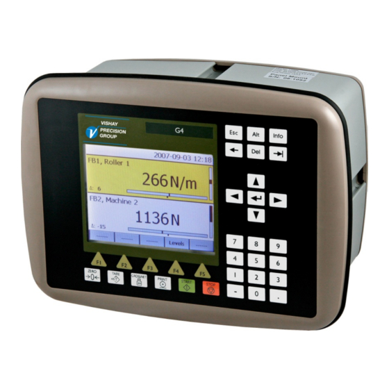
- Page 1 G4 Multi Channel Force Instrument Program version 101.1.0.0 Technical Manual PM/DT/HE types...
-
Page 3: Table Of Contents
G4 Multi Channel Force Instrument Contents Use of inputs and outputs ...... 6-7 1. Introduction Filter function ......... 6-8 Manual updates ........1-1 7. Communication General ..........1-1 Functions ..........1-2 General ..........7-1 Maintenance ........... 1-3 Serial interface ........7-1 Safety information ........ - Page 4 Technical Manual PRECAUTIONS READ this manual BEFORE operating or servicing this instrument. FOLLOW these instructions carefully. SAVE this manual for future reference. WARNING Only permit qualified personnel to install and service this instrument. Exercise care when making checks, tests and adjustments that must be made with power on.
-
Page 5: Introduction Manual Updates
G4 Multi Channel Force Instrument 1. Introduction Manual updates This manual is updated for the 101.1.0.0 program version. In this program is a web server added which enables for the user to access the instrument using a PC running a web browser. -
Page 6: Functions
Technical Manual It is possible to access the instrument, set-up and maintenance functions, remotely over the Ethernet connection using a Web Browser on a connected PC. It is possible to load new software into the instrument using the USB port. All functions in the G4 Instrument are controlled by set-up parameters. - Page 7 G4 Multi Channel Force Instrument Instrument modes. In normal operation mode the G4 Instrument is presenting the measurement values on the front panel graphical display. One or more Function Blocks can be shown simultaneously. The user can configure the display via set-up parameters. During parameter set-up the instrument will continue normal operation.
-
Page 8: Maintenance
Technical Manual Maintenance The G4 instrument needs no maintenance, performed by the end-user. Any service or repair work must be performed by qualified personnel. Contact your supplier. Cleaning Before cleaning the G4, break the power connection to the instrument. Use a soft cloth to clean the exterior of the instrument. For cleaning the instrument front panel a soft, damp cloth may be used. -
Page 9: Technical Data
G4 Multi Channel Force Instrument Technical data Enclosure PM - Panel mount DT –Desktop HE – Harsh types Environment Enclosure Aluminum housing, Aluminum housing, Stainless steel housing, design plastic panel plastic panel plastic panel Dimensions See figure See figure See figure Panel thickness: 2 –... - Page 10 Technical Manual PM -Panel mount enclosure outlines and panel cutout. DT -Desktop enclosure outlines HE - Harsh environment enclosure outlines...
- Page 11 G4 Multi Channel Force Instrument Module type CPU module RTC backup battery Manufacturer Type Lithium battery Panasonic-BSG CR2032 CR2032 3V GP Batteries CR2032 Varta CR2032 (V) COM1 (RS232) and For process data and control Isolated by operational insulation COM2 (RS485) Protocol Modbus RTU Baud rate...
- Page 12 Technical Manual AC SUPPLY Module type Power supply module Input voltage 110-240 V~ +10% -15% including fluctuations, 50/60 Hz, 40W Output voltage 24 V output 0.1 A WF IN / WF IN2 Module type Weight/Force input module Max. # of transducers 8 (350 ohm) per channel Maximum 48 transducers per instrument Excitation voltage:...
- Page 13 G4 Multi Channel Force Instrument HS WF2 Module type High Speed Weight/Force input module Max. # of transducers 4 (350 ohm) per channel Excitation voltage: 10 VDC A/D conversion: 20 kHz, 16 000000 units (24 bits) Input range +/- 4.5 mV/V 25 −...
- Page 14 Technical Manual AOUT1 / AOUT4 Module type Analog output module Number of channels 1 or 4 channels, separately isolated by operational insulation Resolution 65000 units, 16 bits Voltage output 0 – 10 V, -10 – 10 V, > 1 kohm load Current output 4 –...
- Page 15 G4 Multi Channel Force Instrument DeviceNet Module type DeviceNet fieldbus adaptor Connector 5 pin male connector. Baudrate 125, 250, 500 kbps or Auto. Set by parameter. Address 0 – 63, set by parameter Fieldbus data 16 bytes from fieldbus to instrument. 32 –...
-
Page 16: Ordering Information
DC power supply AC power supply Software (note 1) (No code specified) Standard Weighing Program Standard Weighing Program Standard Force Program Special Program (note 2) Example: G4-PM-0-4-8-0-0-0-0-D-F • G4 instrument (G4) • Panel mount (PM) • No fieldbus (0) •... - Page 17 G4 Multi Channel Force Instrument Separate modules Spec.no Module type Module name 110 544 CPU unit 110 546 HS WF2 High speed dual Weight/Force input module 110 547 WF IN Single Weight/Force input module 110 548 WF IN2 Dual Weight/Force input module 110 549 AOUT1 Single channel analog output module...
- Page 18 Technical Manual 1-14...
-
Page 19: Installation Mechanical Installation
G4 Multi Channel Force Instrument 2. Installation Mechanical installation See chapter ‘1. Introduction – Technical data’ for references to PM, DT and HE mechanical measures: outer extents, body extents and panel cutout (PM). PM type instrument: Make sure the panel thickness meets the specification and that there is room enough behind the panel for the instrument and the connected cables (minimum 200 mm). -
Page 20: Electrical Installation
Technical Manual Electrical installation The field wiring of the instrument shall be suitable to the environment (e.g. chemically) in the end-user application. Mains cables shall be separated and routed away from SELV or SELV-E field wiring. For DT and HE instruments UL Listed and KAM cord type flexible cables shall be used. The cable diameters must be selected in accordance with the strain relief specification. -
Page 21: Cpu Unit
G4 Multi Channel Force Instrument CPU unit External computing devices connected to the CPU communication interfaces of the instrument have to comply with the standard, UL 60950. The internal battery in the CPU module is to be used only in the equipment where servicing of the battery circuit and replacement of the lithium battery will be done by a trained technician. - Page 22 Technical Manual Field Bus Slot for optional Fieldbus interface Profibus DP-V1 and DeviceNet are available. See section Profibus-DP Fieldbus Adaptor or DeviceNet Fieldbus Adaptor later in this chapter for details. Connector for USB device(s). This port has no operational insulation and should be considered as a SELV/SELV-E circuit.
-
Page 23: Dc Supply 24 V
G4 Multi Channel Force Instrument DC SUPPLY 24 V Power supply unit The output of the external DC source must be rated 24 V , ±15% including fluctuations, min. 40 W. The DC source must provide Double Insulation between Mains parts and 24 V SELV or SELV-E Circuit, and a limited-energy circuit (maximum available current of 8 A). -
Page 24: Ac Supply
Technical Manual AC SUPPLY – 110-240 V Power supply unit Mains supply cable shall be separated and routed away from SELV or SELV-E field wiring. Remove power before removing the module from the instrument. Make sure the fixation screws are well tightened during operation. 110-240 V~ In Terminals 1, 2 and 3. -
Page 25: Wf In, Wf In2 And Hs Wf2
G4 Multi Channel Force Instrument WF IN, WF IN2 and HS WF2 The voltage levels on connectors of I/O modules shall not exceed hazardous voltage levels of 30 Vrms, 42.4 Vpeak or 60 Vdc under normal conditions. In wet locations these voltage levels shall not exceed 16 Vrms, 22.6 Vpeak or 35 Vdc. - Page 26 Technical Manual 4-wire connection Transducer input, ch. 2 Exc.+ Exc+ Exc.- Sign.+ Sense+ Sign.- Transducer Exc- Sense- Sign+ Sign- Shield Junction box 6-wire connection Transducer input, ch. 1 Exc.+ Exc+ Exc.- Sign.+ Sense+ Sign.- Transducer Exc- Sense- Exc.+ Exc.- Sign+ Sign.+ Sign.- Transducer...
- Page 27 G4 Multi Channel Force Instrument Digital inputs Terminals 6 – 9 and terminal 5 (ICom) as a common connection. Four digital inputs are provided, with functions that can be set in the G4 set-up. External sourcing (24 V ) from the instrument power supply (max. 100 mA) or from a separate DC supply must be used.
-
Page 28: Aout1 And Aout4
Technical Manual AOUT1 and AOUT4 The voltage levels on connectors of I/O modules shall not exceed hazardous voltage levels of 30 Vrms, 42.4 Vpeak or 60 Vdc under normal conditions. In wet locations these voltage levels shall not exceed 16 Vrms, 22.6 Vpeak or 35 Vdc. -
Page 29: Dio8
G4 Multi Channel Force Instrument DIO8 The voltage levels on connectors of I/O modules shall not exceed hazardous voltage levels of 30 Vrms, 42.4 Vpeak or 60 Vdc under normal conditions. In wet locations these voltage levels shall not exceed 16 Vrms, 22.6 Vpeak or 35 Vdc. -
Page 30: Profibus-Dp Fieldbus Adaptor
Technical Manual Profibus-DP Fieldbus Adaptor Profibus module front view (1) Operation mode LED. (2) Status LED. (3) Profibus connector. PROFIBUS DP-V1 Operation mode LED State Indication Not online / No power Green On-line, data exchange Flashing Green On-line, clear Flashing Red (1 flash) Parameterization error Flashing Red (2 flashes) Profibus configuration error... - Page 31 G4 Multi Channel Force Instrument Profibus connector (DB9F) Signal Description B line Positive RxD/TxD, RS485 level Request to send GND Bus Ground (isolated) + 5V Bus Output +5V termination power (isolated) A line Negative RxD/TxD, RS485 level Housing Cable shield Internally connected to the Anybus protective earth via cable shield filters according to the Profibus standard.
-
Page 32: Devicenet Fieldbus Adaptor
Technical Manual DeviceNet Fieldbus Adaptor DeviceNet module front view (1) Network Status LED. (2) Module Status LED. (3) DeviceNet connector. DeviceNet (Pin 1) Network Status LED State Indication Not online / No power Green On-line, one or more connections are established Flashing Green (1 Hz) On-line, no connections established Critical link failure... - Page 33 G4 Multi Channel Force Instrument DeviceNet connector Signal Description Negative bus supply voltage CAN L CAN low bus line Shield Cable shield CAN H CAN high bus line Positive bus supply voltage For connection of the adaptor to the DeviceNet master, use a standard cable for DeviceNet, or similar shielded cable with twisted pairs and a connector according to the diagram below.
-
Page 34: Front Panel
Technical Manual Front panel Display At normal operation the instrument displays force/web tension value(s) and, in some cases, graphic bars representing the displayed values. If an instrument error occurs, the measuring function is stopped and the instrument switches over to Error mode, indicating a code for the error at the display window. If there is a force input error this is indicated with error information that replace the information on the screen for a specific Function Block only, other Function Blocks are not affected. - Page 35 G4 Multi Channel Force Instrument Name Function TARE Not used in the standard Force Instrument. GROSS/NET Not used in the standard Force Instrument. PRINT Not used in the standard Force Instrument ZERO Setting all input Force values for a Function Block to zero. Note that a specific Function Block must be selected.
- Page 36 Technical Manual 2-18...
-
Page 37: Instrument Functionality General
G4 Multi Channel Force Instrument 3. Instrument Functionality General This chapter describes the functionality of the different parts of the force instrument. Function Block All measuring functions in the instrument are based on configurable function blocks. A Function Block is used to calculate the force or web tension of one to four inputs and the sums and differences if more than one input is used. - Page 38 Technical Manual Force Mode The following table and figures explains the function and the values from a Function Block in force mode (set-up parameter ‘X:Web Tension Mode’ = Off). A ‘(F)’ in the table below indicates a force value. 1 Channel 2 Channel 4 Channel Value...
- Page 39 G4 Multi Channel Force Instrument Web Tension Mode A Function Block can be configured for web tension measuring by setting set-up parameter ‘X:Web Tension Mode’ to On. In this case some of the force values will be recalculated to a web tension value using the ‘X:Web Tension Factor’ as shown below. Web Tension Value = Force Value / Web Tension Factor If the Force Values are correctly calibrated in the desired measuring direction then the ‘Web Tension Factor’...
- Page 40 Technical Manual Input A Output 3 Output 7 Output 1 1 / WTF Output 4 Input B Difference Input C Output 5 Output 2 1 / WTF Output 8 Input D Output 6 WTF = Web Tension Factor Four Channel Function block, Web Tension mode Common values The following table explains the available input values to a Function Block.
-
Page 41: Set-Up General
G4 Multi Channel Force Instrument 4. Set-up General All operating functions in the G4 Instrument are controlled by parameters. The parameter values are permanently stored in the instrument and will not be lost when the unit is switched off. At delivery the parameters are factory-set to default values, giving the instrument an initial standard function. -
Page 42: Graphical Touch Display
Technical Manual module, 21 to 28 correspond to inputs on slot 2 I/O and so on. The actual number of inputs depends on what type of I/O-module that is installed in the respective slots. A DIO8 module has 8 inputs a WF IN2 module has 4 inputs while an AOUT1 or AOUT4 has no inputs. - Page 43 G4 Multi Channel Force Instrument Parameter Set-up menu To enter Parameter Set-up, select this sub menu with up/down arrow keys. The selected sub menu is then highlighted. Press ‘Enter’ to open the selected sub menu or just tap on the desired sub-menu to open it. If there isn’t room for all parameters on screen, it is possible to scroll trough the list with the scroll bar at...
- Page 44 Technical Manual When editing a choice parameter e.g. language as in the figure, a list of available choices is show on screen with the current selection highlighted. To change the selection the up/down arrow keys can be used. It is also possible to directly make a choice by tapping on the desired selection.
- Page 45 G4 Multi Channel Force Instrument...
-
Page 46: Menu Structure
Technical Manual Menu structure Main Menu *sub menu *Levels *Clock Set-up *Parameter Set-up *System Information *Maintenance *Network Configuration (Cont. on next page) Levels Clock Set-up Parameter Set-up *General Level values for *Hardware Config. Date and time set-up configured levels *Calibration *Communication *Level Supervision *Inputs... - Page 47 G4 Multi Channel Force Instrument (from previous page) System Information Maintenance Network Configuration *Diagnostics Information on serial *IP Configuration *File Handling numbers, program *Server Configuration *Create Backup versions, network *Restore Backup status and installed *Set Default Values I/O modules. *Program Upgrade (from previous page) Inputs Outputs...
-
Page 48: Parameters
Technical Manual Parameters On the following pages a survey of all parameters is presented. The parameters are divided in groups following the menu they belong to. For choice parameters the available choices are given. For numerical parameters, a value range is given. At the end of the table, the default value is given in <... - Page 49 G4 Multi Channel Force Instrument Range/Alternatives Explanation and <default value> result of alternatives. Date Format YYYY-MM-DD Defines the date format. YYYY-DD-MM YYYY: = year. MM: = month. DD: = day. DD-MM-YYYY MM/DD/YYYY <YYYY-MM-DD> Time Format 12 h Defines the time format. 24 h 12 h: 12 hour time format.
- Page 50 Technical Manual Range/Alternatives Explanation and <default value> result of alternatives. Menu ‘Hardware Config.’ Fieldbus Not In Use This parameter defines what type of fieldbus that will be used in Profibus the CPU. DeviceNet Not In Use: The fieldbus is not used regardless of any installed <Not In Use>...
- Page 51 G4 Multi Channel Force Instrument Range/Alternatives Explanation and <default value> result of alternatives. Func. Block 1 Type Not In Use This parameter defines if Function Block 1 is used and, if used, 1 Channel the no of inputs it should use. 2 Channel Not In Use: The Function Block is not used.
- Page 52 Technical Manual Range/Alternatives Explanation and <default value> result of alternatives. F.Block 1 Inp.C < Not In Use > This parameter defines which measuring channel (slot and channel) that should be use as input C to Function Block 1. See ‘F.Block 1 Inp. A.’ for a description of parameter values. Note: this parameter is only shown if ‘Function Block 1 Type’...
- Page 53 G4 Multi Channel Force Instrument Range/Alternatives Explanation and <default value> result of alternatives. F.Block 2 Inp.C < Not In Use > This parameter defines which measuring channel (slot and channel) that should be used as input C to Function Block 2. See ‘F.Block 1 Inp.
- Page 54 Technical Manual Range/Alternatives Explanation and <default value> result of alternatives. F.Block 3 Inp.C < Not In Use > This parameter defines which measuring channel (slot and channel) that should be used as input C to Function Block 3. See ‘F.Block 1 Inp. A.’ for a description of parameter values. Note: this parameter is only shown if ‘Function Block 3 Type’...
- Page 55 G4 Multi Channel Force Instrument Range/Alternatives Explanation and <default value> result of alternatives. Menus ‘Function Block 1’ – ‘Function Block 8’ The Calibration menu contains up to 8 sub menus, one for each used Function Block. The parameters are the same for all 8 menus. Here only Function Block 1 parameters are shown.
- Page 56 Technical Manual Range/Alternatives Explanation and <default value> result of alternatives. 1:Measurement Unit NONE Defines the unit that should be used for measured force value(s) and for related set-up parameters. kN/m inch feet mV/V <N> 1:Resolution 0.001 Defines the decimal point position and resolution format for the 0.002 displayed force value.
- Page 57 G4 Multi Channel Force Instrument Range/Alternatives Explanation and <default value> result of alternatives. 1:Web Tension Unit NONE Defines the unit that should be used for measured web tension value(s) and for related set-up parameters. kN/m Note: this parameter is only shown if ‘1:Web Tension Mode‘ is set to ‘On’...
- Page 58 Technical Manual Range/Alternatives Explanation and <default value> result of alternatives. 1:HSWF Update Rate 25 Hz Defines the update rate for the measuring channel belonging to 50 Hz Function Block 1 if the force conversion module is of HS WF 2 100 Hz type.
- Page 59 G4 Multi Channel Force Instrument Range/Alternatives Explanation and <default value> result of alternatives. 1:A Value Cal. P1 Range: +/–999999 This parameter defines, for Input A, the load in the lowest Unit: calibration point, normally 0. Measurement Unit Note: This parameter is not shown if parameter ‘F.Block 1 Inp.A’ <0>...
- Page 60 Technical Manual Range/Alternatives Explanation and <default value> result of alternatives. 1:B Value Cal. P1 Range: +/–999999 This parameter defines, for Input B, the load in the lowest Unit: calibration point, normally 0. Measurement Unit Note: This parameter is only shown if parameter <0>...
- Page 61 G4 Multi Channel Force Instrument Range/Alternatives Explanation and <default value> result of alternatives. 1:C Value Cal. P1 Range: +/–999999 This parameter defines, for Input C, the load in the lowest Unit: calibration point, normally 0. Measurement Unit Note: This parameter is only shown if parameter <0>...
- Page 62 Technical Manual Range/Alternatives Explanation and <default value> result of alternatives. 1:D Value Cal. P1 Range: +/–999999 This parameter defines, for Input D, the load in the lowest Unit: calibration point, normally 0. Measurement Unit Note: This parameter is only shown if parameter <0>...
- Page 63 G4 Multi Channel Force Instrument Range/Alternatives Explanation and <default value> result of alternatives. Menu ‘Serial Com.’ Modbus Address Range: 1 to 247 Defines the instrument Modbus address. <1> COM1:Mode Not in use Defines use of serial port Com 1. Modbus Slave Not in use: The port is not used.
- Page 64 Technical Manual Range/Alternatives Explanation and <default value> result of alternatives. COM1:Floating Point Format Modicon Float Sets how the Modbus slave should handle floating point values. Float Modicon Float: Modicon floating point format. < Modicon Float > Float: IEEE 32 bit floating point format See chapter 7 ‘Communication’...
- Page 65 G4 Multi Channel Force Instrument Range/Alternatives Explanation and <default value> result of alternatives. COM2:Floating Point Format Modicon Float Sets how the Modbus Slave should handle floating point values. Float Modicon Float: Modicon floating point format. < Modicon Float > Float: IEEE 32 bit floating point format. See chapter 7 ‘Communication’...
- Page 66 Technical Manual Range/Alternatives Explanation and <default value> result of alternatives. Menu ‘Fieldbus’ Note: The Fieldbus menu is not shown if parameter ‘Fieldbus‘ (in Hardware Config menu) is set to ‘Not In Use’. See chapter 7 ‘Communication − Fieldbus interface’ for more details on fieldbus configuration and usage.
- Page 67 G4 Multi Channel Force Instrument Range/Alternatives Explanation and <default value> result of alternatives. Data Block 1 Type Not In Use Sets the data source for Data Block 1. Selections Sum/Difference Sum/difference, Output 1-2, Output 3-4, Output 5-6, Output 7 -8, Output 1-2 Input A-B Force, Input C-D Force, Input A-B Signal and Output 3-4...
- Page 68 Technical Manual Range/Alternatives Explanation and <default value> result of alternatives. Data Block 1 Format Floating Point Sets the Data Block 1 Format. Integer Floating Point: The Data Block data format is floating point. < Floating Point > Integer: The Data Block format is integer. Note: This parameter is only shown if parameter ‘No Of Data Blocks‘...
- Page 69 G4 Multi Channel Force Instrument Range/Alternatives Explanation and <default value> result of alternatives. Menus ‘Level 1’ – ‘Level 32’ NOTE: There are 32 levels each with the following parameters described below. Level 1 Source ( - Level 32 Source) Not in use Defines the signal to be supervised by the Level Supervisor.
- Page 70 Technical Manual Range/Alternatives Explanation and <default value> result of alternatives. Level 1 Function Block ( - Level 32 Function Block) Defines which Function Block that will be supervised by the level. 1: The level is supervising Function Block number 1. 2: The level is supervising Function Block number 2.
- Page 71 G4 Multi Channel Force Instrument Range/Alternatives Explanation and <default value> result of alternatives. Menus ‘Inputs Slot 1’ - ‘Inputs Slot 6’ NOTE: There are six possible sub menus, one for each slot. In each slot sub menu there are up to 8 possible inputs named 11 to 18 for slot 1, 21 to 28 for slot 2 and so on.
- Page 72 Technical Manual Range/Alternatives Explanation and <default value> result of alternatives. Menus ‘Outputs Slot 1’ - ‘Outputs Slot 6’ NOTE: There are six possible sub menus, one for each slot. In each slot sub menu there are up to 8 possible outputs named 11 to 18 for slot 1, 21 to 28 for slot 2 and so on.
- Page 73 G4 Multi Channel Force Instrument Range/Alternatives Explanation and <default value> result of alternatives. Menu ‘Analog Outputs’ NOTE: There are 4 possible analog outputs each with the parameters described below. If the selected analog output module is AOUT4 there will be parameters for four analog outputs displayed, if the AOUT1 is selected only the parameters for the first analog output (shown below) will be shown.
- Page 74 Technical Manual Range/Alternatives Explanation and <default value> result of alternatives. AOUT 1 Function Block (- AOUT 4 Function Block) 1: Function Block number 1 uses this analog output. 2: Function Block number 2 uses this analog output. …. 8: Function Block number 8 uses this analog output. Note: This parameter is not shown if parameter ‘AOUT 1 Source’...
- Page 75 G4 Multi Channel Force Instrument Range/Alternatives Explanation and <default value> result of alternatives. AOUT 1 Bandwidth (- AOUT 4 Bandwidth) 1.6 Hz Sets the analog output bandwidth. 3 Hz Note: This parameter is not shown if parameter ‘AOUT 1 Source’ 6 Hz is set to ‘Not in use’.
- Page 76 Technical Manual 4-36...
-
Page 77: Calibration General
G4 Multi Channel Force Instrument 5. Calibration General When measuring with the G4 Instrument, the transducer output signal, corresponding to the transducer load, is converted to a force value. The conversion is controlled by several parameters with values defined during calibration of the individual Function Blocks. -
Page 78: Common Parameters
Technical Manual If the G4 Instrument must be replaced, a table calibration of the replacement unit can be performed, with recorded values from an earlier calibration. To get the best accuracy, a ‘Known Force’ calibration with known force to at least 2/3 of the used range, should be performed. -
Page 79: Calibration Using Datasheet
G4 Multi Channel Force Instrument Calibrating using datasheet When calibrating with data given in the transducer data sheet the ‘Table calibration’ method should be used. Note that there are two different ways that the transducer characteristics may be described in a data sheet. Choose the appropriate method below. -
Page 80: Using Parameters Values From A Previous Calibration
Technical Manual Using parameter values from a previous calibration When calibrating with data from a previous calibration the ‘Table calibration’ method should be used. This is performed by entry of recorded force values and corresponding transducer signal values into the instrument. The accuracy of the copying procedure is 0.005 %. -
Page 81: Calibration With Known Forces
G4 Multi Channel Force Instrument Calibration with known forces When calibrating with known forces applied to the transducers the ‘Known Force calibration’ method should be used. This is normally the most accurate calibration type. The transducer signals are measured and automatically stored when the input is loaded with known force. - Page 82 Technical Manual...
-
Page 83: Operation General
G4 Multi Channel Force Instrument 6. Operation General This version of G4 instrument with strain gauge transducers is designed mainly for force and web tension purposes. The measurement values are displayed at the front panel, and can also be transmitted to a master computer/PLC. The measurement values can also be presented as the output signal from an analog output module. - Page 84 Technical Manual Display alternatives by normal operation In the operating display it is possible to view force/web tension information from one or more function blocks. It is also possible to select which function block that shall be displayed on the color touch display. With parameter ‘Display modes’ it is possible to select what combinations of the three operating display modes that can be selected by the operator.
- Page 85 G4 Multi Channel Force Instrument 2007-08-02 10:41 -502 : -27 FB2, Roller 5 1250 : 16 ------ ------ P.Tare Levels ------ Two function blocks operating display mode. 2007-08-02 10:41 -502 : -27 FB2, Roller 5 1250 : 16 1835 : 45 6895 : -67 ------...
-
Page 86: Security Locks
Technical Manual Security locks In the G4 instrument two security locks are included to prevent unauthorised access to the instrument via the panel keys. The locks can be activated by parameters in menu ‘Main menu/Parameter set-up/General’. The following requires a login password if the corresponding lock is on. Changing instrument clock: Operator lock. -
Page 87: Main Menu
G4 Multi Channel Force Instrument Main menu To reach the main menu, press the ‘Info’ button on the instrument front panel. Navigating in a menu is done with arrow keys or by tapping on the display on specific choices e.g. ‘Parameter set-up’. To open a sub menu, e.g. -
Page 88: Level Supervision
Technical Manual Level supervision The G4 instrument contains 32 supervision Levels that can be used to supervise defined signals in the instrument. Digital outputs can be connected as outputs for the Levels. The properties for each Level are configured by set-up parameters. Functions for Level supervision are defined in menu ‘Parameter Set-up’... -
Page 89: Use Of Inputs And Outputs
G4 Multi Channel Force Instrument ‘Level X Up Delay’ Defines the Delay time for increasing signal. The level will switch when the supervised value has been above Level X value during the set delay time. It is possible to use delay and hystereses concurrently, but it is recommended to set the hystereses to zero when the ‘Level X Up Delay’... -
Page 90: Filter Function
Technical Manual Filter function In the instrument the measured values are filtered according to the settings chosen by the user during set-up. The filter settings can be selected from a wide range. This means that the instrument can be configured from very stable indication to more fast response but with less stable readings depending on the demands from the actual application. - Page 91 G4 Multi Channel Force Instrument HS WF2 module filter Update rate - 3 dB damping Damping at -40° phase shift frequencies ≥ fs / 2 (fs) frequency frequency ≥ 20 dB 800 Hz ++ 87 Hz 21 Hz ≥ 90 dB 800 Hz 48 Hz 10 Hz...
- Page 92 Technical Manual 6-10...
-
Page 93: Communication General
G4 Multi Channel Force Instrument 7. Communication General The G4 Instrument has two serial communication ports, one Ethernet port and an optional fieldbus module. The serial communication ports, the Ethernet port and the optional fieldbus interface module are used for communication with a control unit. Serial interface The instrument is equipped with 2 serial communication ports: COM1, COM2. -
Page 94: Modbus Tcp Slave
Technical Manual Setup of Modbus RTU communication • The instrument will as default be given the address 1. If more than one instrument is used in a network, each G4 instrument must be given a unique address in parameter ‘Modbus address’ (in ‘Parameter set-up’, menu ‘Communication’, sub menu ‘Serial Com’). -
Page 95: Modbus Protocol
G4 Multi Channel Force Instrument Modbus protocol For communication with a master computer (PLC) the Modbus protocol is used in the instrument. The Modbus protocol is a standard protocol, used for master/slave communication in the industry. Information is transmitted in blocks of data to minimise polling and response time delays. - Page 96 Technical Manual General registers The G4 instrument has a number of Modicon 'Holding Registers' (registers 4XXXX ... ). The Modbus function 03 'Read Holding Registers' should be used to read these registers and the Modbus function 05 'Preset Single Register' or 16 'Preset Multiple Registers' should be used to write to the registers.
- Page 97 G4 Multi Channel Force Instrument Data type: Data type: float Explanation Integer (2 reg./value) 40062 (1 reg) 44062 Function Block 3: Error code 40063 (1 reg) 44064 Function Block 3: Status 40064 (3 reg) 44066 Function Block 3: Sum 40067 (3 reg) 44068 Function Block 3: Difference 40070 (3 reg)
- Page 98 Technical Manual Data type: Data type: float Explanation Integer (2 reg./value) 40132 (1 reg) 44122 Function Block 8: Error code 40133 (1 reg) 44124 Function Block 8: Status 40134 (3 reg) 44126 Function Block 8: Sum 40137 (3 reg) 44128 Function Block 8: Difference 40140 (3 reg) 44130...
- Page 99 G4 Multi Channel Force Instrument Data type: Data type: float Explanation Integer (2 reg./value) 40217 (3 reg) 44200 Function Block 2: Output 2 40220 (3 reg) 44202 Function Block 2: Output 3 40223 (3 reg) 44204 Function Block 2: Output 4 40226 (3 reg) 44206 Function Block 2: Output 5...
- Page 100 Technical Manual Data type: Data type: float Explanation Integer (2 reg./value) 40312 (3 reg) 44266 Function Block 3: Input C Signal (mV/V) 40315 (3 reg) 44268 Function Block 3: Input D Signal (mV/V) 40318 (1 reg) 44270 Function Block 4: Error code 40319 (1 reg) 44272 Function Block 4: Status...
- Page 101 G4 Multi Channel Force Instrument Data type: Data type: float Explanation Integer (2 reg./value) 40400 (3 reg) 44330 Function Block 5: Output 7 40403 (3 reg) 44332 Function Block 5: Output 8 40406 (3 reg) 44334 Function Block 5: Input A Force 40409 (3 reg) 44336 Function Block 5: Input B Force...
- Page 102 Technical Manual Data type: Data type: float Explanation Integer (2 reg./value) 40488 (3 reg) 44394 Function Block 7: Sum 40491 (3 reg) 44396 Function Block 7: Difference 40494 (3 reg) 44398 Function Block 7: Output 1 40497 (3 reg) 44400 Function Block 7: Output 2 40500 (3 reg) 44402...
- Page 103 G4 Multi Channel Force Instrument Data type: Data type: float Explanation Integer (2 reg./value) 40583 (3 reg) 44460 Function Block 8: Input D Force 40586 (3 reg) 44462 Function Block 8: Input A Signal (mV/V) 40589 (3 reg) 44464 Function Block 8: Input B Signal (mV/V) 40592 (3 reg) 44466 Function Block 8: Input C Signal (mV/V)
- Page 104 Technical Manual Data type: Data type: float Explanation Integer (2 reg./value) 42022 (3 reg) 46018 Level 5 value 42025 (3 reg) 46020 Level 6 value 42028 (3 reg) 46022 Level 7 value 42031 (3 reg) 46024 Level 8 value 42034 (3 reg) 46026 Level 9 value 42037 (3 reg)
- Page 105 G4 Multi Channel Force Instrument Instrument type This register holds the type of the instrument. For a G4 Multi Channel Force Instrument this value is 4002. Standard program major and minor version This registers holds the major and minor version for a standard program. Special program major and minor version This registers holds the major and minor version for a special program.
- Page 106 Technical Manual Instrument error This register holds the overall error code for the instrument. Normally this register should contain ‘00’ which means no error. Instrument status This register holds the overall status for the instrument Bits set to 1 in this register have the following meaning: Bit no Function Comment Remote operation...
- Page 107 G4 Multi Channel Force Instrument Function Block X: Error code This register holds the first error code for a Function Block. Normally this register should contain ‘000’ which means no error. Error codes 000 to 255 and 000 to X255 are valid in this register, where X (1-4) indicates which input channel (A-D) the three digit error code belongs to.
- Page 108 Technical Manual Function Block X: Sum This register holds the sum value for a Function Block. The actual use of the sum value varies with type of Function Block. The value should not be read alone because the status and error codes are stored in other registers.
- Page 109 G4 Multi Channel Force Instrument These registers holds the values sent to the analog outputs. The registers can be used for fault finding in the system. Note: The value is rounded to 3 decimals. Status of inputs 11-18, 21-28 Bits set to 1 in this register have the following meaning: Bit no Function Bit no Function...
- Page 110 Technical Manual Status of inputs 31-38, 41-48 Bits set to 1 in this register have the following meaning: Bit no Function Bit no Function Digital input 31 activated. Digital input 41 activated. Digital input 32 activated. Digital input 42 activated. Digital input 33 activated.
- Page 111 G4 Multi Channel Force Instrument Status of outputs 11-18, 21-28 Bits set to 1 in this register have the following meaning: Bit no Function Bit no Function Digital output 11 activated. Digital output 21 activated. Digital output 12 activated. Digital output 22 activated. Digital output 13 activated.
- Page 112 Technical Manual Status of outputs 51-58, 61-68 Bits set to 1 in this register have the following meaning: Bit no Function Bit no Function Digital output 51 activated. Digital output 61 activated. Digital output 52 activated. Digital output 62 activated. Digital output 53 activated.
- Page 113 G4 Multi Channel Force Instrument Level status 17-32 Bits set to 1 in this register have the following meaning: Bit no Function Comment Above level 17 The supervised signal is above Level 17. Above level 18 The supervised signal is above Level 18. Above level 19 The supervised signal is above Level 19.
- Page 114 Technical Manual Command register As this register is read, the answer will always contain only zero's. There are a number of actions that can be activated in the instrument. The value of this register (when different from zero) will activate one of these actions, as described in below.
- Page 115 G4 Multi Channel Force Instrument Level X value These registers are used to read and write levels that are supervised by the instrument. I/O bits (Coils) The instrument has a number of I/O bits that the master can write to using Modbus function 05 or 15.
- Page 116 Technical Manual Data representation Data sent to and from the instrument uses 16 bit holding registers (40XXX) and can use different formats for flexibility. Integer Unsigned integer (1 modbus register) Values stored in one modbus register as an unsigned integer (16 bit number without decimals).
- Page 117 G4 Multi Channel Force Instrument Float values The type of float values used in the communication is selected in the set-up for the different communication interfaces. Values stored as standard IEEE 32 bit float values. Each value has two registers assigned to it.
- Page 118 Technical Manual Exception responses When the master sends a query to a slave it expects a normal response (as described earlier). One of the following three events occur after a query from the master. 1. Normal response. The slave has received the query without communication error and can handle the query normally.
- Page 119 G4 Multi Channel Force Instrument Supported Modbus functions Function Description Reads the state of discrete outputs (0X references, coils). Only implemented because some 'masters' use this function to initiate Read Coil Status communication. Coil range: 1 – 16 (Max number of points to read: 16). Response: Zero (OFF) for all requested points.
-
Page 120: Fieldbus Interface
Technical Manual Fieldbus interface The optional fieldbus interface is based on a network communication module from HMS Industrial Networks. Available fieldbusses are Profibus and DeviceNet. With setup parameters the fieldbus interface is configured for the specific needs of an installation. It is possible to setup address, baud rate (if applicable to the actual fieldbus type) and mapping of the memory area in the fieldbus module that is available to the network. - Page 121 G4 Multi Channel Force Instrument Data from the fieldbus (Outputs in the master) General This 16 bytes block is mandatory, i.e. it is always mapped to the fieldbus in the instrument. Byte Contents Command Number of registers to write Start address, Read/Write Start address, Read/Write Write register 1 Write register 1...
- Page 122 Technical Manual Bytes 2 and 3: Define from which register number to read or write. Bytes 4 to 15: Contains the data when writing to the instrument. Data to the fieldbus (Inputs in the master) General Data to the fieldbus are divided into two categories, one is the mandatory “base block” which contain general data and the 12 modbus register used for reading from the instrument.
- Page 123 G4 Multi Channel Force Instrument The first 32 bytes of data from the instrument to the fieldbus are mandatory. Bytes 0 and 1: Contains the actual instrument error information (the value 0 means no error). See ‘7. Communication – Modbus protocol – Instrument error’. Bytes 2 and 3: The actual status information for the instrument, see ‘7.
- Page 124 Technical Manual Configurable data blocks Data Blocks is used to transfer data from the Byte Contents instrument to the master. Up to 12 data Start of data block 1 blocks can be used. Each block consists of 16 bytes. The data blocks have fixed Start of data block 2 positions in memory, see list below.
- Page 125 G4 Multi Channel Force Instrument Function Block sum and difference values data block Byte Contents (Floating-point format) Contents (Integer format) Offset + 0 Function Block x: Error code Function Block x: Error code Offset + 1 Function Block x: Error code Function Block x: Error code Offset + 2 Function Block x: Error code...
- Page 126 Technical Manual Function Block Output 1 and Output 2 values data block Byte Contents (Floating-point format) Contents (Integer format) Offset + 0 Function Block x: Error code Function Block x: Error code Offset + 1 Function Block x: Error code Function Block x: Error code Offset + 2 Function Block x: Error code...
- Page 127 G4 Multi Channel Force Instrument Function Block Input A Force and Input B Force values data block Byte Contents (Floating-point format) Contents (Integer format) Offset + 0 Function Block x: Error code Function Block x: Error code Offset + 1 Function Block x: Error code Function Block x: Error code Offset + 2...
- Page 128 Technical Manual Function Block Input A Signal and Input B Signal values data block Byte Contents (Floating-point format) Contents (Integer format) Offset + 0 Function Block x: Error code Function Block x: Error code Offset + 1 Function Block x: Error code Function Block x: Error code Offset + 2 Function Block x: Error code...
- Page 129 G4 Multi Channel Force Instrument Level status Byte Contents (Floating-point format) Contents (Integer format) Offset + 0 Level status 1 – 16 Level status 1 – 16 Offset + 1 Level status 1 – 16 Level status 1 – 16 Offset + 2 Level status 1 –...
- Page 130 Technical Manual Input Status (Floating-point format) Byte Content Offset + 0 Status of inputs 11 – 18, 21 – 28 Offset + 1 Status of inputs 11 – 18, 21 – 28 Offset + 2 Status of inputs 11 – 18, 21 – 28 Offset + 3 Status of inputs 11 –...
- Page 131 G4 Multi Channel Force Instrument Output Status (Floating-point format) Byte Content Offset + 0 Status of outputs 11 – 18, 21 – 28 Offset + 1 Status of outputs 11 – 18, 21 – 28 Offset + 2 Status of outputs 11 – 18, 21 – 28 Offset + 3 Status of outputs 11 –...
- Page 132 Technical Manual Inp./Outp Status (Integer format) Byte Content Offset + 0 Status of inputs 11 – 18, 21 – 28 Offset + 1 Status of inputs 11 – 18, 21 – 28 Offset + 2 Status of inputs 31 – 38, 41 – 48 Offset + 3 Status of inputs 31 –...
- Page 133 G4 Multi Channel Force Instrument AOUT1-4 Value (Floating-point format) Byte Content Offset + 0 Analogue output value 1 Offset + 1 Analogue output value 1 Offset + 2 Analogue output value 1 Offset + 3 Analogue output value 1 Offset + 4 Analogue output value 2 Offset + 5 Analogue output value 2...
- Page 134 Technical Manual AOUT1-2 Value (Integer format) Byte Content Offset + 0 Analogue output value 1, int Offset + 1 Analogue output value 1, int Offset + 2 Analogue output value 1, int Offset + 3 Analogue output value 1, int Offset + 4 Analogue output value 1, dec Offset + 5...
- Page 135 G4 Multi Channel Force Instrument AOUT3-4 Value (Integer format) Byte Content Offset + 0 Analogue output value 3, int Offset + 1 Analogue output value 3, int Offset + 2 Analogue output value 3, int Offset + 3 Analogue output value 3, int Offset + 4 Analogue output value 3, dec Offset + 5...
- Page 136 Technical Manual Examples Example 1: Setting ‘Level 1 Value’ to 123.5 (Writing to float value register). 1. Make sure that the previous command was not 251. Set command byte (00) to 0 if previous command was 251. 2. Set number of registers (2) to write in byte 01. 3.
- Page 137 G4 Multi Channel Force Instrument Example 3: Set read window to read floating point data from Function Block 2 (registers 44050 to 44061). Note that the number of registers read is always 12. 1. Make sure that the previous command was not 250. Set command byte (00) to 0 if previous command was 250.
- Page 138 Technical Manual 7-46...
-
Page 139: Remote Access General
G4 Multi Channel Force Instrument 8. Remote Access General Using a PC with a Web Browser, like MS Internet Explorer, it is possible to get access to the instrument set-up and maintenance functions. The PC can be connected to the same network as the instrument, or directly with an Ethernet crossover cable. -
Page 140: Using The Remote Access
Technical Manual Using the Remote Access To navigate in the menu system a mouse, touch pad, pointing stick etc. must be used. The keyboard cannot be used for navigation. Hovering with the mouse pointer over a selection in a menu will highlight the item and clicking will open the next menu level or allow for a parameter to be edited. -
Page 141: Remote Access Login And Logout
G4 Multi Channel Force Instrument Remote Access Login and Logout Entering the IP Address of the desired instrument in the address field of the browser will have the instrument Web Server presenting the login form, see the picture below. Login form The user ID is always ‘G4User’... - Page 142 Technical Manual When the correct login credentials are entered the entry screen will be displayed. This picture will show the Instrument Name (if set) or possible start up errors (serious or fatal errors). Any errors shown here must normally be corrected from the instrument and not through remote access.
- Page 143 G4 Multi Channel Force Instrument Live screen Logged out screen Clicking the ‘Close the Window’ text will close the browser (if allowed by the browser). Note that the browser may save the login credentials which then are proposed as default next time the user tries to login to the same unit. When a remote access session is finished the user should log out from the entry screen before closing the browser.
-
Page 144: Remote / Local Access
Technical Manual interfere with another Remote Access user unconscious. Note that if a user has been idle for 30 min he will be logged out automatically. Next user to log in will continue from the same position in the menu system. Override screen Remote / Local Access It is possible to access the menu system both locally and remotely simultaneously. -
Page 145: Remote Set-Up
G4 Multi Channel Force Instrument Remote Set-up All operating functions in the G4 Instrument are controlled by parameters. The parameter values are permanently stored in the instrument and will not be lost when the unit is switched off. At delivery the parameters are factory-set to default values, giving the instrument an initial standard function. - Page 146 Technical Manual Main Menu To reach the main menu the user first has to connect to the instrument by entering the IP Address and then (if required) entering the login user ID (G4User) and the password (default 1937, possible to change). This will display the Entry Screen and by clicking the ‘Menu’...
- Page 147 G4 Multi Channel Force Instrument This example shows the ‘General’ parameter menu but editing is done similar throughout the menu system. To edit a parameter, simply click on it. If all items in the menu don’t fit on the screen, it is possible to scroll through the list of parameters using the scroll bar at the right of the screen.
-
Page 148: Remote Access Maintenance
Technical Manual When editing a numerical parameter e.g. a level hystereses setting as in the figure, the new value should be typed with the keyboard numerical keys. To confirm the new value click the ‘Enter’ button on the screen. To abort editing and keep the previous setting, click the ‘Escape’ button. Editing a value parameter Remote Access Maintenance General... - Page 149 G4 Multi Channel Force Instrument Function Blocks Shows information about all used function blocks, one at the time. Values with the unit ‘--‘ are not used in the current configuration of the function block and in case of error the five lines in the middle (‘Sum:’ to ‘Outp. 4’) will be replaced by an error message.
- Page 150 Technical Manual Communication Shows status for the two serial ports, the External I/O and the Modbus TCP Slave. The serial ports COM1 and COM2 can be ‘Not In Use’, ‘Modbus RTU Slave’ or ‘Printer. In the example below ‘COM1:’ is not used and ‘COM2:’ is in Modbus RTU Slave mode with address 1, 115200 baud, 8 data bits, no parity and 1 stop bit.
- Page 151 G4 Multi Channel Force Instrument Fieldbus Shows the fieldbus type, address and status of the optional Fieldbus interface. It also gives the possibility to study the contents in selected parts of the instrument memory (data to and from the fieldbus master). The function is very useful for advanced fault finding in case of problems with the fieldbus communication.
- Page 152 Technical Manual Digital Inputs Shows the status of digital inputs. Digital inputs are numbered 11 – 68. Each row corresponds to a slot. Only the currently available inputs in each slot are shown. The first field on each line is the input numbers for the line and the following digits indicates status of the inputs.
- Page 153 G4 Multi Channel Force Instrument Digital Outputs Shows the status of digital outputs. It is also possible to change the status of the digital outputs. The digital outputs are numbered 11 – 68. Each row corresponds to a slot. Only the currently available outputs in each slot are shown.
- Page 154 Technical Manual Analog Outputs Shows the output value or a possible error message for installed analog outputs. It is also possible to override the normal operation and set the output value for each analog output. To change an output value click the button marked with the output number and enter wanted value.
- Page 155 G4 Multi Channel Force Instrument File Handling menu The file handling has access to the ‘user tree’ directory structure in the instrument. The default folders are ‘InstrBackup’, ‘LogFiles’, ‘Misc’ and ‘Recipes’. The folder ‘InstrBackup’ is used as default when creating or restoring backup and the folder ‘LogFiles’...
- Page 156 Technical Manual Restore Backup Restoring a previously stored parameter backup to the instrument. Any additional information in the backup file is displayed before a backup file is restored. Backup files are fetched from the PC. Using the Restore Backup requires either a Set-up Code or an Operator Code if a lock is activated.
- Page 157 G4 Multi Channel Force Instrument Instrument Restart With the instrument restart function it is possible to force the instrument to make complete restart (corresponding to a power down – power up cycle). This must be used with great caution especially if done from a remote position. The user must make sure that no hazardous situation will occur.
- Page 158 Technical Manual 8-20...
-
Page 159: Maintenance General
G4 Multi Channel Force Instrument 9. Maintenance General The Maintenance menu includes a number functions used for diagnostics, maintenance and program upgrade purposes. The Maintenance menu is found under the Main menu. Diagnostics The diagnostics functions covers Function Blocks, Communication, Fieldbus, Digital Inputs, Digital Outputs and Analog Outputs. - Page 160 Technical Manual When a correct message is received on an interface the corresponding header text will blink. In the example below ‘COM1:’ is not used and ‘COM2:’ is in Modbus RTU Slave mode with address 1, 115200 baud, 8 data bits, no parity and 1 stop bit. Communication COM1: Not In Use COM2: Modbus RTU Slave, 1, 115200, 8, N, 1...
- Page 161 G4 Multi Channel Force Instrument Digital Inputs Shows the status of all installed digital inputs. The first field on each line is the input numbers for each card slot in the instrument and the following digits indicates the current available inputs in the slot. A ‘0’ indicates that the input is passive and a ‘1’...
-
Page 162: File Handling
Technical Manual Analog Outputs Shows the output value or a possible error message for all installed analog outputs. It is also possible to override the normal operation and set the output value for each analog output. To change an output value press the function key marked with the output number and enter wanted value. -
Page 163: Program Upgrade
G4 Multi Channel Force Instrument Program Upgrade Upgrading the program with a different version. Upgrading is normally done from a USB memory. When upgrading the user is asked to select the version to upgrade to by selecting an ‘Upgrade.txt’ file that is situated within the folder containing all files and folders necessary for program upgrade. - Page 164 Technical Manual...
-
Page 165: Troubleshooting General
G4 Multi Channel Force Instrument 10. Troubleshooting General During installation and maintenance of the G4 Instrument, the sub menus ‘System Information’ and ‘Maintenance / Diagnostics’ can be useful for solving possible problems related to I/O modules, Ethernet, Serial Communication etc. The instrument reports detected errors on the display. - Page 166 Technical Manual Force errors The indication is either temporary or stays on until the cause is cured. Error Explanation code No error. The instrument is in ‘normal state’ and no error is detected. x003 Instrument not in normal state. Force/Web Tension values are not valid. x005 Over range Over range means that the input signal from the transducer exceeds...
- Page 167 G4 Multi Channel Force Instrument Start-up errors These error codes can only appear during start-up. Error Explanation code Set-up data error Indicates faulty set-up. Enter set-up mode, perform the necessary editing and save the new parameter settings or use the “Set Default values” function (Maintenance menu).
- Page 168 Technical Manual General errors These errors generally occur due to faulty entries from the front panel, alternatively invalid data or not allowed commands from the control unit. Error Explanation code Input channel not used The Input channel is not configured (used) in the instrument. Function Block not used The Function Block is not configured (used) in the instrument.
- Page 169 G4 Multi Channel Force Instrument Set-up errors These errors occur only during instrument set-up from the front panel. Certain errors depend on more than one set-up parameter and it is the operator’s responsibility to locate and correct all faulty set-up parameters. Error Explanation code...
-
Page 171: Appendix 1
G4 Multi Channel Force Instrument Appendix 1. - Page 172 Technical Manual...
- Page 174 Document no. 35148 Article no. 600 895 R3 © Vishay Nobel AB, 2011-09-30 Subject to changes without notice. Vishay Nobel AB Vishay BLH Box 423, SE-691 27 Karlskoga, Sweden Edgewater Drive, Norwood, MA 02726, USA Phone +46 586 63000 · Fax +46 586 63099...
Need help?
Do you have a question about the G4-PM and is the answer not in the manual?
Questions and answers