
Subscribe to Our Youtube Channel
Summary of Contents for KUKEN PTS-800 EX
- Page 1 Operation Manual Read this Operation Manual thoroughly and the separate "Instruction Manual" before using. KUKEN CO., LTD.
-
Page 2: Table Of Contents
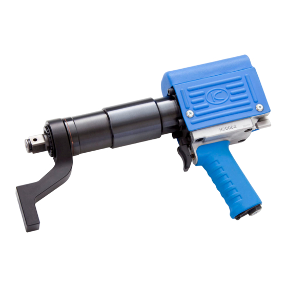
Table of Contents Main Unit : Part Name and Functions Controller : Part Name and Functions Unique Functions Preparation ( 1 ) Attaching Accessory Preparation ( 2 ) - ① Initial Setting (Description) Preparation ( 2 ) - ② Initial Setting (Operation) Preparation ( 3 ) How to Set The Torque How to Fasten ( Industrial [Ind] Mode ) How to Loosen ( Industrial [Ind] Mode ) How to Fasten Wheel Nuts ( Automotive [Aut] Mode ) How to Loosen Wheel Nuts ( Automotive [Aut] Mode ) Troubleshooting ( 1 ) Troubleshooting ( 2 ) Description of Error Code Troubleshooting ( 3 )-① ( CH1 ) Troubleshooting ( 3 )-② ( CH1 ) Cautions for Operation Option Main Unit & Controller Unit Specifications... - Page 3 Main Unit : Part Name and Functions Battery Box Stores 4 AA batteries to operate the controller unit. The Controller To see the torque and to set the torque. Reaction Force Absorber (Option) To absorb the reaction force. Ensure to place the reaction Force Absorber next to the reaction point. Reverse Lever Switches the rotation direction [right (R) / left (L)]. Throttle Button Starts / stops the machine.
- Page 4 Controller Unit : Part Name And Functions JUDGMENT LAMP OK (GREEN) : Lights when the fastening is completed successfully. NG ( RED ) : Lights when the set torque cannot be obtained due to interruption or error. Display Panel Displays the torque + and - keys Uses to change the torque. Pre-set keys Uses to select the pre-set torque. SETUP Lamp (Red) Lights when changing the pre- set torque or the pre-set key. Power Key Uses to turn on manually when the power is off.
-
Page 5: Unique Functions
If not operating for a certain period of time, the power will be turned off automatically. ③ REAL TIME DISPLAY The torque can be shown on the panel in real time and easy to understand the situation. ④ LOOSENING FUNCTION AUTOMOTIVE MODE [Aut] and INDUSTRIAL MODE [Ind] can be selected for loosening operations. ⑤ JUDGMENT LAMP The fastening result can be judged if the operation is successful or not. If the operation is successfully completed, the judgment lamp turns green. If the operation is suspended or stopped, the NG lamp turns and alerts its under-torque. ⑥ AUTO SHUT OFF The solenoid valve shuts off and stops the machine when the operation is completed successfully and the judgment lamp turns green. Safety Functions ① Fail Safe Function In case batteries are exhausted or very low, the CPU will not be activated but the spindle turns very slowly to reverse direction. Operators can easily recognize the battery problem. ② Error Detection Function, Abnormal Fastening Detection [ CH1 ] This function detects bolt stretching beforehand and forces to stop the machine. This function can be turned on/off depending on works. ③ Function to Prevent Operational Error This function is to prevent an operational error. The key which is set [ - - - ] and selected by mistake will never be operated. Other Functions ① Power Source CPU is operated by batteries. Use 6 of AA dry cell batteries. Alkaline (recommended) and also Ni-MH is available. ② Data Transmission ( Option ) PTS can be connected to a computer or the printer ( option ) with the KUKEN original transmission cable ( option ) to transfer results. PTS must be the transmission model ( option ) in order to transfer data. -
Page 6: Preparation ( 1 )
Preparation (1) Attaching Accessories Check to make sure that all the components are present and that nothing is damaged in shipping. If any problems, please contact your dealer. Insert batteries into PTS. Coupling Plug 20PM・・・・・・・・・・・・・・・・・・・・・ 1 ● Unscrew and open the battery housing cover and Spiral Retainer Ring ・・・・・・・・・・・・・・・・・・・・ 1 ● insert batteries. AA Dry Cell Alkaline Battery ・・・・・・・・・・・・ 6 ● Be sure to insert correct directions of batteries. (If not using long, remove batteries) Attach the coupling plug. WARNING Do not insert batteries opposite directions. Inserting batteries opposite directions will damage the CPU. Attach the reaction force absorber (option). Attach the socket. Attach the reaction force absorber and then attach the spiral retainer ring for PTS-800EX, the o-ring for PTS-800EXL. "O" Ring Spiral Retainer Ring Make sure to attach the impact socket. "O" Ring Warning Make sure that the air supply is disconnected when attaching the reaction force absorber. ・ Make sure that the spiral retainer ring and the "O" ring is properly attached to avoid the ・ reaction force absorber or the socket to be come off. Operating PTS-800EX / PTS-800EXL without a reaction force absorber may cause injuries. ・ Please do not operate PTS-800EX / PTS-800EXL without a reaction force absorber. -
Page 7: Preparation (2)-①
Preparation (2)-① Initial Setting ( Description ) Before using PTS, following modes must be selected. (1) Selection of Transmission Mode ( Transmission Model is optional ). There are 2 types of PTS models. Transmission model and non-transmission model. If non-transmission model, either mode below may be selected. ① PRINTER MODE [ Prn ] ・・・・・・・Connect the printer ( option ) to out put the result on thermal paper. ② PC MODE [ PC ] ・・・・・・・Connect a computer to transfer results (2) Selection of [ Loosening ] Mode [ Automotive ] and [ Industrial ] must be selected depending on usage. application Automotive Mode Industrial Mode Panel Display Direction Right / Left handed screws Right handed screws only Maximum Torque Up to the pre-set torque Up to the pre-set torque selected currently selected currently Maximum Torque Up to the pre-set torque Up to 800 Nm for Loosening selected currently Press ④ of the display panel How to Set [ - L - ] will be shown. Turn the reverse lever to LEFT. Loosening Mode To continue loosening works, The Loosening Mode is automatically set. -
Page 8: Preparation (2)-②
Preparation (2)-② Initial Setting ( Operation ) This section describes how to select and set each mode. Please follow the instruction below. ① Make sure the machine is turned off. keep on pressing Press ③ for a few second and press the power switch while pressing ③. Press to turn on To select Transmission Mode ② Press ① key once to change the mode from the [Prn]. And press ① again to change the mode back to [PC] If the PTS is non-transmission model, either can be selected. ③ Press ② to complete the selection. Then the selection will move to the next setting. To select Loosening Mode ④ Press ① key once to change the mode from the [Aut]. And press ① again to change the mode back to [Ind]. ⑤ Press ② to complete the selection. Then the selection will move to the next setting. To select [ CH1 ] Mode ⑥ Press ① key once to change the mode from the [CH1] on. And press ① again to change the mode back to [CH-] off. ⑦ Press ② to complete the selection. After the selection of [CH1], the power will be turned off. -
Page 9: Preparation ( 3 )
Preparation (3) How to Set The Torque This section describes how to pre-set the torque for keys ① through ④. For example, to pre-set ① with 600 Nm. ① Turn on the power switch and make sure the display blinks. Press ① key for 3 seconds. Release ② SETUP Lamp lights up and the display indicates the pre-set key and then the previous torque. (This figure shows 500 Nm as the previous torque). As soon as the torque is displayed, release the finger from the key. Lights up ③ Press [ + ] or [ - ] key to change the value to 600. Pressing [ + ] for a few seconds increases the value quickly. Pressing [ - ] for a few seconds decreases the value quickly. ④ To complete the setting, press [ SET ] ② key. ● Please make sure the display blinks [ 0 ] after setting. To pre-set other keys, repeat above method ① through ④. Once pre-set the torque, the value is stored until re-set the torque. (Caution) The torque range is 400 to 800 Nm. The torque can not be set beyond the range. Function to Prevent Operational Error ① Select the pre-set key and press [ - ] until the lowest limit. ② When [ - - - ] is displayed, the pre-set key is set to prevent operational error. Even though the pre-set key which is set [ - - - ] is selected by mistake, the tool will not be able to operated. The CPU will be turned off after 10 seconds, but the torque value will be fixed. -
Page 10: How To Fasten
How to Fasten Industrial Mode [Ind] Selecting the pre-set number ( for example, the pre-set number ① and 600Nm ) Blinking ① Press the power switch. The display shows [ 0 ] blinking. ② Press ① for a few seconds. The pre-set ① is set 600 Nm. When the display indicates ① [ P.1 ], release the key. Soon after indicating [ P.1 ], the display also indicate the torque value [ 600 ] Nm. At this moment, the pre-set key ① is selected. Selected pre-set key is valid until changing to other pre-set key. ③ Check the rotative direction ( Reverse Lever ). R : Right Rotation L : Left Rotation (Fastening the right (Fastening the handed screw) left handed screw Reverse for [Aut] mode) Lever ④ After placing the reaction force absorber next to the fastening bolt/nut, insert the socket to the fastening bolt/nut and press the throttle lever. ( Caution ) ・ In case of right handed screw, the reaction force absorber rotates to the direction (A). ・ In case of left handed screw, direction (B) Reaction Force Absorber In case of fastening In case of fastening the the right handed left handed screw. screw ( [Aut] mode only ) - Page 11 How to Fasten Industrial Mode [Ind] ⑤ Press the throttle button to start fastening. Rotating the nut at the high speed until the nut bottom out. When bottoms out, the rotation speed is switched to low to continue While operating, the torque will the fastening. be shown in real time. ⑥ Once reaches the pre-set torque, OK lamp will be lit ( green ) and stops automatically. light up The final attained torque blinks on the display panel. blinking *1 When reaching the set torque, the machine automatically stops and rotates in the reverse direction at an ultra-low speed immediately to prevent the socket bite. Immediately release your hand from the throttle button when the counter-rotating starts. ⑦ If the throttle lever is released while operating, NG lamp ( red ) will be lit to alert the operator. When the throttle button is released or interrupted due to finger slipping, make sure to re-fasten the nut. Otherwise, check the set torque and the set mode. Warning ・ While operating PTS, do not touch the reaction force absorber or the socket. ・ If something wrong with PTS, please release the throttle button and stop the operation.
-
Page 12: How To Loosen
How to Loosen ( 2 ) Industrial Mode [Ind] The maximum loosening torque for [ Ind ] mode is 800 Nm. ① Turn the Reverse Lever to the left. L : Reverse direction ( Loosening the right handed screw) Reverse Lever ② Apply the reaction force absorber next to the fastening bolt/nut. And press the throttle lever. Lights While loosening, [ - L - ] will be displayed. If exceeding the maximum torque 800 Nm, will be displayed and the torque limiter will shut off the machine. In this case, please use an impact wrench to loosen the bolt/nut. Warning ・ While operating PTS, do not touch the reaction force absorber or the socket. ・ If something wrong with PTS, please release the throttle button and stop the operation. -
Page 13: How To Fasten Wheel Nuts
How to Fasten Wheel Nuts Automotive Mode [ Aut ] mode Selecting the pre-set number ( for example, the pre-set number ① and 600Nm ) ① Press the power switch. The display shows [ 0 ] blinking. Blinking ② Press ① for a few seconds. The pre-set ① is set 600 Nm. When the display indicates ① [ P.1 ], release the key. Soon after indicating [ P.1 ], the display also indicate the torque value [ 600 ] Nm. At this moment, the pre-set key ① is selected. Selected pre-set number is valid until changing to other pre-set number. ③ Check the rotative direction ( Reverse Lever ). L : Left Rotation R : Right Rotation (Fastening the left (Fastening the handed screw) left handed screw) Reverse ④ Apply the reaction force absorber next to the fastening bolt/nut. Then apply the socket to the fastening bolt/nut. - Page 14 How to Fasten Wheel Nuts Automotive Mode [ Aut ] mode ⑤ Press the throttle button to start fastening. Rotating the nut at the high speed until the nut bottom out. When bottoms out, the rotation speed is switched to low to continue While operating, the torque will the fastening. be shown in real time. ⑥ Once reaches the pre-set torque, OK lamp will be light up lit ( green ) and stops automatically. The final attained torque blinks on the display panel. blinking *1 When reaching the set torque, the machine automatically stops and rotates in the reverse direction at an ultra-low speed immediately to prevent the socket bite. Immediately release your hand from the throttle button when the counter-rotating starts. ⑦ If the throttle lever is released while operating, NG lamp ( red ) will be lit to alert the operator. When the throttle button is released or interrupted due to finger slipping, make sure to re-fasten the nut. Otherwise, check the set torque and the set mode. In case of the wheel nut made up of the inner nut and the outer nut, CAUTION!! please make sure the following. Make sure to fasten the inner nut securely before fastening the outer nut. ● Since this machine absorbs the reactive force by the (inner or outer) nut, fasten all nuts after ● sufficiently inserted in order to protect the thread. ○ × Nut is sufficiently inserted. Nut is not sufficiently inserted.
-
Page 15: How To Loosen Wheel Nuts ( Automotive [Aut] Mode )
How to Loosen Wheel Nuts Automotive Mode [ Aut ] mode In case of [ Aut ] mode, the maximum loosening torque is the pre-set torque. In case of the wheel nut made up of the inner nut and the outer nut, please be careful that CAUTION!! the inner nut may be loosen while loosening the outer nut. Please make sure to fasten inner nut securely before fastening the outer nut. ① Turn the reverse lever to each direction. ・ In case of right handed screw, turn the reverse lever to the left. ・ In case of left handed screw, turn the reverse lever to the right Right direction Left direction (loosening the left handed screw) (loosening the right handed screw) ② When the power is turned on, the display shows blinking blinking [ 0 ] blinking. Then press ③ to loosen operation. When the display shows the [ - L - ] blinking, the loosening operation is ready. To cancel the loosening operation, press ③. ・ [ - L - ] will be shown only for 10 seconds. After the 10 seconds, the power will be turned off. ③ Apply the reaction force absorber next to the loosening nut and light up press the throttle lever to start operating. While loosening, [ - L - ] will be displayed. Soon after the loosening is completed, turn the reverse lever back to fastening position. To continue loosening operation, repeat this method for each nut. Once the loosening operation is completed, the mode will be back to the fastening. will be shown on the display if excesses the maximum torque (no more than pre-set torque) and the machine will be turned off automatically. In this case, please use an impact wrench to loosen the nut. -
Page 16: Troubleshooting ( 1 )
Troubleshooting (1) Symptom/Panel Display Causes Measures Air pressure is decreased when Eliminate the cause and check the Torque displayed on the panel operating. air compressor or others. does not reach the pre-set Check the pre-set torque and re-set torque. ( *1 ) The torque can be set incorrectly. the value again. Main Unit Reaches to the pre-set torque Abnormality on the thread surface Replace the nut/bolt with new one. and stops automatically before (due to seizure of thread or others) the nut/bolt is bottomed out. Even though the throttle lever is Batteries are not inserted. Insert batteries. pressed, the spindle slowly rotates in the reverse direction against the Batteries are not properly placed Battery rotative direction (Reverse Lever). in the battery housing. Securely set batteries in place. is displayed. ( *2 ) Batteries are running low. Replace batteries with new ones. is displayed and turned Controller off immediately. Failure of the controller (CPU). Please refer the next page. (XX is indicated with 2 digit number) ( *2 ) -
Page 17: Troubleshooting ( 2 )
Troubleshooting (2) Description of Error Code ● Error Code Description on PTS main unit ( troubles on the main unit ) Error Code Panel Display Causes Measures Malfunction of the torque sensor causes Please contact your dealer. the misalignment of ''zero point''. The sensor detects the abnormal uprising Please check the surface of screws of the torque higher than the pre-set and grease and fasten again. torque. However [E02] is still shown on the panel, please contact your dealer. Low batteries Please replace with new batteries. ● Error Code Description on fastening Error Code Panel Display Causes Measures If [ CH1 ] is turned on, Please see the next page [ Troubleshooting (3) ]. (CHECK1) Result below pre-set torque Releasing the throttle lever before reaching Please loosen the nut once and try Under the pre-set torque. to fasten again. Torque (The figure shows 350Nm when releasing the throttle lever). ● Error Code Description on loosening Error Code Panel Display Causes... - Page 18 Troubleshooting (3)-① [CH1] Depending on the condition of wheels, bolts, nuts and other fastening parts, fastening with PTS may damage bolts. ○ ( Hereinafter this condition will be referred to as "abnormal fastening"). This machine has the function to immediately detect this "abnormal fastening" and shut down to prevent bolts and ○ other parts from damages. When "abnormal fastening" is detected, "CH1"( CHECK1 ) is displayed on the controller and the machine stops. ○ When "CH1" ( abnormal fastening ) is displayed, check the following. ○ 【1】If "CH1"(abnormal fastening) is displayed, please remove the nut. (Caution) If the wheel nut is made up of the inner nut and the outer nut, please make sure to fasten the inner nut with recommended torque after loosening the outer nut. If "CH1" is displayed, do not continue fastening. Loosen the bolt / nut first. Warning Otherwise the bolt may be stretched or the wheel may be deformed. Misalignment 【2】 In case of JIS type ( 8 nuts ) Center of Center (1) Whether the wheel center is misaligned to the wheel bolt. (2) Whether there are any damages on the seating surface of wheels, nuts, and or thread face. ● Replace the parts when there are damages or unevenness of seating face. Wheel Bolt Wheel Hole (3) Whether the wheel bolt is extended ( stretched ). ● If so, replace the bolt with new one. (4) Whether excessive grease is applied. ●...
- Page 19 Troubleshooting (3)-② [CH1] 【3】 In case of ISO type ( 10 nuts ) (1) Whether there are any damages on the seating surface of wheels, nuts, and or thread face. ● Replace the parts when there are damages or unevenness of seating face. (2) Whether the wheel bolt is extended ( stretched ). ● If so, replace the bolt with new one. (3) Whether appropriate amount of grease is applied or excessive grease is applied. ● Excessive grease application is a cause of excessive axial force generation. Pay full attention to the amount and the portion applied. Refer automobile manufacturer's instruction. ● For the tapered area, apply grease to the degree that the excessive grease does not leak when the nut and the washer are pressed. If excessive, wipe the grease off gently with a waste cloth. (4) Whether the torque is appropriate. ● Refer automobile manufacturer's instruction. 【4】 After examine bolts, nuts and others for abnormality or changing to new parts, please fasten nuts with extra pre-tightening. (Caution) If the wheel nut is made up of the inner nut and the outer nut, please make sure to fasten the inner nut with recommended torque after loosening the outer nut.
- Page 20 Cautions for operation ① In any case, do not touch the reaction force absorber and the socket when operating. ② If anything wrong with the machine, immediately release hands from throttle button to stop operation. ③ Always keep the working air pressure within the range of 0.6 to 0.7 MPa (Pe). Usage under the air pressure of over 0.7 Mpa may cause the defect of the built-in solenoid valve. ④ Avoid excessive grease application on the air motor. It may cause the defect of the built-in solenoid valve. (As a guideline, apply "one or two drops of the machine oil ISOVG 10 once a day.") ⑤ When applying the cap of the reactive force absorber to the nut, do not align the absorber by hand. The hand might be pinched between the reactive force absorber and an object by accident when starting the machine. ⑥ Do not operate in the condition that the socket of the reactive force absorber and the socket of the main unit are not properly inserted into the respective nuts. The socket or reactive force absorber may come off the nut, resulting in human injuries and damage on the nut and the object. ⑦ Do not pour "liquid" or "oil" onto the controller. ⑧ Do not make a high impact on the controller. ⑨ In case the machine does not stop when the OK lamp is on, it might be at fault. Stop using the machine immediately. ⑩ Replace batteries when the power is off. ⑪ In case of tightening, fastening may be completed with a little larger torque than the pre-set torque. ( When exceeding the specified upper limit of torque by tightening, once loosen the nut and re-fasten it from the beginning.) Do not insert batteries opposite directions. Warning Inserting batteries opposite directions will damage the CPU. ⑫ Use AA dry cell batteries X 4. Alkaline (recommended), Ni-MH(rechargable), Oxyride dry batteries are applicable. Do not use other batteries than specified. Do not use worn batteries. Carefully read cautions on batteries and follow the direction. ◎ Following cases may cause human injury, liquid leaking of batteries, excessive heat of batteries, or burst of batteries Do not peel the exterior package of the battery or scratch the battery. ● Using those batteries may cause the heat or burst.
- Page 21 Options ● Reactive Force Absorber Any kind of reactive force absorber is available to design and make. Please ask your dealer. ● Hanging Metal This is also the optional part which is very convenient to keep the machine hanging. Hanging Metal Transmission ● PTS-800ES can be connected to the printer or the computer(*1). And the result can be saved as data. original printer (option) original printer cable [ PTS-PRN ] (option) PTS-800EX / 800EXL Transmission Model (*2) original transmission cable 10m (option) original software [ PTS-COM ] (option) (*1) PTS can not be connected both the printer and the computer at same time. (*2) PTS-800EX / EXL must be the transmission model in order to connect the printer or the computer.
- Page 22 Printer Output ( PTS-PRN ) ● By connecting the optional printer, it enables to print the pre-set key number and the pre-set torque, the direction, ● the result, and a company name/facility name. ( The company name/facility name must be registered at KUKEN and must be within 24 letters. ) But the date or the operation time will not be printed. If using the printer, please refer Page 7 and select [ Prn ]. ● PC Output ( PTS-COM ) ● By the installation of the optional software ( PTS-COM ) to a computer, ● ① Displays the torque, the number of screws, and the date on the computer screen. Also it enables to save in the computer file as data. ② Fastening history can be read in Excel format. ① ③ The torque chart ( time - torque ) can be displayed and saved in the computer. If using a computer, please refer Page 7 and select [ PC ]. ● ② ③...
- Page 23 Main Unit Specifications (controller included) PTS-800EX PTS-800EXL Length 404 mm 15.9 in 457 mm 18 in Weight ** 6.4 kg 14.1 lbs 6.7 kg 14.7 lbs. Free Speed 100 r.p.m. 100 r.p.m. Air Consumption 0.38 m /min 13.5 c.f.m. 0.38 m /min 13.5 c.f.m. Drive Size 1" Sq. 1" Sq. ** Reactive force absorber, socket, and batteries not included. Controller Specifications Use Environment Ambient temperature : 0 - 50 ℃ Humidity : 20 - 95 % ( non condensing ) Fastening Method Torque method Parameters to be set Set torque, fastening mode ( right hand screw/left hand screw ) Resolution 1 Nm Set Torque Range 400 - 800 Nm 1Nm/step Accuracy ± 5% Display Numeric representation 0 - 999 3 digit LED with 7 segments Displayed by x 1Nm Judgment Lamp...
- Page 24 ΚΟΙΝΟΤΗΤΑΣ We KUKEN CO.,LTD. -Osaka, Japan declare under our sole responsibility that the product: to which declaration relates, is in conformity with the requirements of the Council Directive of 22 June 1998 on the approximation of the laws of the Member States relating to machinery(2006/42/EC).
Need help?
Do you have a question about the PTS-800 EX and is the answer not in the manual?
Questions and answers