Advertisement
Quick Links
System Power Amplifier (SPA)
Installation Guide
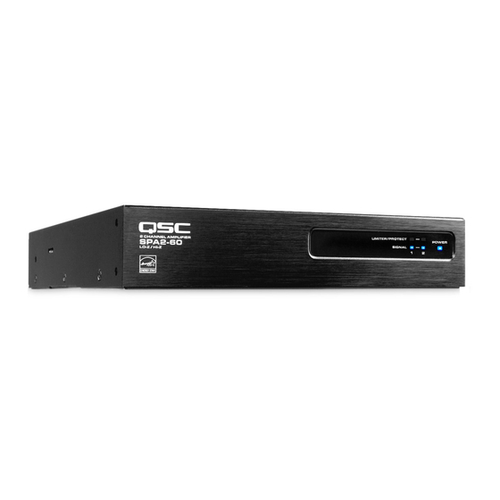
SPA2-60 Amplifi er
SPA2-200 Amplifi er
The term "WARNING!" indicates instructions regarding personal safety. If the instructions are not followed the result may be bodily injury or death.
The term "CAUTION!" indicates instructions regarding possible damage to physical equipment. If these instructions are not followed, it may result in
damage to the equipment that may not be covered under the warranty.
The term "IMPORTANT!" indicates instructions or information that are vital to the successful completion of the procedure.
The term "NOTE" is used to indicate additional useful information.
The intent of the lightning fl ash with arrowhead symbol in a triangle is to alert the user to the presence of un-insulated "dangerous"
voltage within the product's enclosure that may be of suffi cient magnitude to constitute a risk of electric shock to humans.
The intent of the exclamation point within an equilateral triangle is to alert the user to the presence of important safety, and operating
and maintenance instructions in this manual.
What's in the Box
SPA2-60
SPA2-200
SPA4-60
SPA4-100
Rack-Ear Spacer
QSC P/N
CH-001386-00
Rack-Ear Cover Label
QSC P/N
LB-001138-00
SPA 4-channel (1x)
Plug 3.5 mm,
10 pos, grn
QSC P/N
CO-000647-00
TD-000500-01 -D
*TD-000500-01*
SPA4-60 Amplifi er
SPA4-100 Amplifi er
EXPLANATION OF SYMBOLS
(1x)
AC Power Cord,
US
(2x)
Phillips Pan Head
M4 x 7 mm
(1x)
SPA 2-channel (1x)
SPA 4-channel (2x)
Euro Plug 3.5 mm,
4 pos, grn
QSC P/N
CO-000646-00
SPA 4-channel (1x)
Plug 3.5 mm,
10 pos, grn
QSC P/N
CO-000648-00
(1x)
Rack Ear
QSC P/N
CH-001344-00
(6x)
Phillips Flathead
M3 x 6 mm
SPA 2-channel (1x)
Euro Plug 3.5 mm,
5 pos, grn
QSC P/N
CO-000644-00
Warranty
TD-000453
(2x)
Joining Plate
QSC P/N
CH-001345-00
(6x)
Foam Spacer
QSC P/N
PL-001023-00
SPA 2-channel (1x)
Euro Plug 3.5 mm,
4 pos, blk
QSC P/N
CO-000645-00
(1x)
Safety Information
TD-000337
(2x)
(4x)
(1x)
Advertisement


Need help?
Do you have a question about the SPA2-60 and is the answer not in the manual?
Questions and answers