Advertisement
Quick Links
Advertisement

Related Manuals for Gira 0391


Summary of Contents for Gira 0391
- Page 1 Operating Instructions Room Temperature Controller 24/10 (4) A~ with NC contact 0391 ..
- Page 3 Contents Operating instructions Room temperature controller 24/10 (4) A~ with NC contact...
- Page 4 Installation of the room temperature controller Area of application The room temperature controller is used to control the temperature in closed rooms, such as apart- ments, schools, lecture halls, workshops etc. Installation site • Install the room temperature controller on an inte- rior wall and, if possible, directly across from the heat source.
- Page 5 • Ensure that the normal convective air of the room can reach the room temperature controller unim- peded. For this reason, the controller is not to be mounted within shelf walls or behind curtains or similar coverings. • Heat from other sources negatively influences con- troller precision.
- Page 6 Installation site...
- Page 7 Installation Attention Installation and mounting of electrical devices may only be carried out by a qualified electrician. If the mounting and installation instructions are not complied with, a danger of fire and other dangers can arise. The room temperature controller is mounted in a 58-mm flush-mounted box in accordance with DIN 49 073.
- Page 8 2. Electrical connection in accordance with wiring schematic (see Page 10). 3. Mount device into flush-mounted box with screws. Attention: Always mount support ring on wallpa- per. The support ring may not be wallpapered over when renovating. 4. Set housing cover with cover frame in place. Engage housing cover at the top left in the hous- ing basis and tighten screw.
- Page 9 Electrical connection. Connect all cables in accordance with the wiring schematic (see Page 10). If this is not done, great temperature fluctuations will result, as the room temperature controller cannot work properly. An earthed connection is not required, as the device is double insulated.
- Page 10 Wiring schematic...
- Page 11 Key to wiring diagram L,N= power supply = connection for clock signal for temperature reduction = heating load connection RF = resistance for heat return TA = resistance for night-time heating reduction of room temperature...
- Page 12 Setting the temperature limits Two setting rings are found in the setting knob. You can set the temperature limits as desired with them. The temperature controller is set to the maximum set- ting range of 5 °C to 30 °C at the factory.
- Page 13 3. To set the red setting ring to the upper temper- ature limit (23 °C here): Insert a pointy object (e.g. pen) into one of the holes of the red ring. Rotate the red ring anti- clockwise to 23 °C. The outer numbers of the scale apply here.
- Page 14 4. To set the blue setting ring to the lower temper- ature limit (8 °C here): Insert a pointy object (e.g. pen) into the hole of the blue ring. Rotate the blue ring clockwise to 8 °C. The inner numbers of the scale apply here.
- Page 15 Temperature adjustment When commissioning the room temperature control- ler, note that the thermo-bimetal requires a certain amount of time to adjust to the room temperature. This is why the switching point will deviate from the room temperature immediately after mounting or after night-time heating reduction switches off.
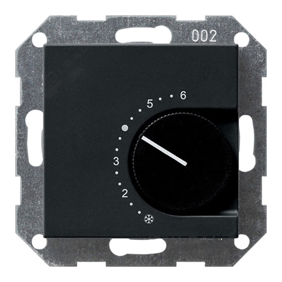
- Page 16 Temperature setting scale The scale for the temperature setting is found on the cover of the room temperature controller and is used for visual orientation when setting the temperature (from min. 5 °C to max. 30 °C). = approx. 5 °C 2 = approx.
- Page 17 Technical data Temperature range: 5 °C to 30 °C Rated voltage: 24 V AC Rated current: 10 (4) A Contact rating: approx. 240 W Switching temperature differential: approx. 0.5 K Night-time heating reductions: approx. 4 K Conductor cross-section: 1 to 2.5 mm solid conductor.
- Page 18 Please submit or send faulty devices postage paid together with an error description to your responsi- ble salesperson (specialist trade/installation com- pany/electrical specialist trade). They will forward the devices to the Gira Service Center.
- Page 20 Gira Giersiepen GmbH & Co. KG Elektro-Installations- Systeme Postfach 1220 42461 Radevormwald Deutschland Tel +49 (0) 21 95 / 602 - 0 Fax +49 (0) 21 95 / 602 - 191 www.gira.de info@gira.de...