JVC KD-S5050 Service Manual
Cd receiver
Hide thumbs
Also See for KD-S5050:
- Instruction manual (59 pages) ,
- Instructions manual (36 pages) ,
- Instructions manual (25 pages)
Advertisement
Quick Links
SERVICE MANUAL
11
2003
MA026
1
PRECAUTIONS . . . . . . . . . . . . . . . . . . . . . . . . . . . . . . . . . . . . . . . . . . . . . . . . . . . . . . . . . . . . . . . . . . . . . . . 1-3
2
SPECIFIC SERVICE INSTRUCTIONS . . . . . . . . . . . . . . . . . . . . . . . . . . . . . . . . . . . . . . . . . . . . . . . . . . . . . . 1-5
3
DISASSEMBLY . . . . . . . . . . . . . . . . . . . . . . . . . . . . . . . . . . . . . . . . . . . . . . . . . . . . . . . . . . . . . . . . . . . . . . . 1-6
4
ADJUSTMENT . . . . . . . . . . . . . . . . . . . . . . . . . . . . . . . . . . . . . . . . . . . . . . . . . . . . . . . . . . . . . . . . . . . . . . . 1-24
5
TROUBLESHOOTING . . . . . . . . . . . . . . . . . . . . . . . . . . . . . . . . . . . . . . . . . . . . . . . . . . . . . . . . . . . . . . . . . 1-25
COPYRIGHT © 2003 VICTOR COMPANY OF JAPAN, LIMITED
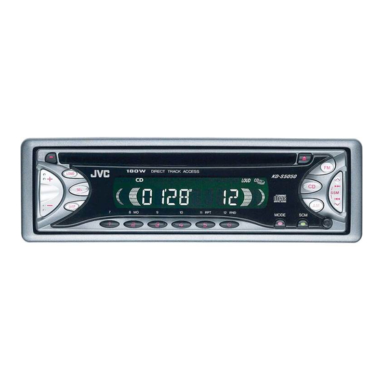
CD RECEIVER
KD-S5050
DIRECT TRACK ACCESS
7
8
9
10
11
TABLE OF CONTENTS
J -------------- Northern America
12
Area suffix
No.MA026
2003/11
Advertisement

Related Manuals for JVC KD-S5050


Summary of Contents for JVC KD-S5050
-
Page 1: Table Of Contents
SERVICE MANUAL CD RECEIVER MA026 2003 KD-S5050 Area suffix J -------------- Northern America DIRECT TRACK ACCESS TABLE OF CONTENTS PRECAUTIONS ............... 1-3 SPECIFIC SERVICE INSTRUCTIONS . - Page 2 SPECIFICATION AUDIO AMPLIFIER SECTION Maximum Power Output Front 45 watts per channel Rear 45 watts per channel 17 watts per channel into 4 Ω, 40 Hz to 20 000 Hz at no Continuous Power Output (RMS) Front more than 0.8% total harmonic distortion. 17 watts per channel into 4 Ω, 40 Hz to 20 000 Hz at no Rear more than 0.8% total harmonic distortion.
-
Page 3: Precautions
SECTION 1 PRECAUTIONS Safety Precautions Burrs formed during molding may be left over on some parts of the chassis. Therefore, pay attention to such burrs in the case of preforming repair of this system. Please use enough caution not to see the beam directly or touch it in case of an adjustment or operation check. - Page 4 Preventing static electricity Electrostatic discharge (ESD), which occurs when static electricity stored in the body, fabric, etc. is discharged, can destroy the laser diode in the traverse unit (optical pickup). Take care to prevent this when performing repairs. 1.2.1 Grounding to prevent damage by static electricity Static electricity in the work area can destroy the optical pickup (laser diode) in devices such as CD players.
-
Page 5: Specific Service Instructions
SECTION 2 SPECIFIC SERVICE INSTRUCTIONS This service manual does not describe SPECIFIC SERVICE INSTRUCTIONS. (No.MA026)1-5... -
Page 6: Disassembly
SECTION 3 DISASSEMBLY Main body 3.1.1 Removing the front panel assembly (See Fig.1) (1) Push the detach button in the lower right part of the front panel assembly and remove the front panel assembly. Front panel assembly Detach button Fig.1 3.1.2 Removing the bottom cover (See Fig.2) (1) Turn the main body up side down. - Page 7 3.1.4 Removing the side panel (See Fig.4) • Prior to performing the following procedure, remove the front panel assembly as required. (1) Remove the screw B and two screws C attaching the heat sink on the left side of the main body, and remove the side panel.
- Page 8 3.1.7 Removing the CD mechanism assembly (See Fig. 7) • Prior to performing the following procedure, remove the front panel assembly, front chassis assembly, side panel, bottom cover, rear bracket, main board and CD mechanism board. (1) Remove the three screws H attaching the top chassis. (2) Take out the CD mechanism assembly.
- Page 9 CD Mechanism Assembly 3.2.1 Removing the top cover (See Figs.1 and 2) (1) Remove the two screws A on the both side of the body. (2) Lift the front side of the top cover and move the top cover backward to release the two joints a. Top cover Joints a Fig.1...
- Page 10 3.2.2 Removing the connector board Wires (See Figs.3 to 5) CAUTION: Before disconnecting the flexible wire from the pickup, solder the short-circuit point on the pickup. No observance of this in- struction may cause damage of the pickup. (1) Remove the screw B fixing the connector board. (2) Solder the short-circuit point on the connector board.
- Page 11 3.2.3 Removing the DET switch (See Figs.6 and 7) (1) Extend the two tabs c of the feed sw. holder and pull out the switch. (2) Unsolder the DET switch wire if necessary. DET switch Connector board Pickup Fig.6 Tab c DET switch DET switch wire Tab c...
- Page 12 3.2.4 Removing the chassis unit (See Figs.8 and 9) • Prior to performing the following procedure, remove the top Chassis unit cover and connector board. Suspension spring (L) Suspension spring (R) (1) Remove the two suspension springs (L) and (R) attaching the chassis unit to the frame.
- Page 13 3.2.5 Removing the clamper assembly (See Figs.10 and 11) • Prior to performing the following procedure, remove the top cover. (1) Remove the clamper arm spring. Clamper arm spring (2) Move the clamper assembly in the direction of the arrow to release the two joints d.
- Page 14 3.2.6 Removing the loading / feed motor assembly (See Figs.12 and 13) • Prior to performing the following procedure, remove the top cover, connector board and chassis unit. (1) Remove the screw C and move the loading / feed motor assembly in the direction of the arrow to remove it from the chassis rivet assembly.
- Page 15 3.2.7 Removing the pickup unit Pickup unit (See Figs.14 to 18) • Prior to performing the following procedure, remove the top cover, connector board and chassis unit. (1) Remove the screw D and pull out the pu. shaft holder from Part e the pu.
- Page 16 3.2.9 Removing the trigger arm Joint k (See Figs.19 and 20) • Prior to performing the following procedure, remove the top cover, connector board and clamper unit. (1) Turn the trigger arm in the direction of the arrow to release Trigger arm the joint k and pull out upward.
- Page 17 3.2.11 Removing the mode sw. / select lock arm Link plate Joint t (See Figs.22 and 23) Mode sw. • Prior to performing the following procedure, remove the top plate assembly. Select lock arm (1) Bring up the mode sw. to release from the link plate (joint t) and turn in the direction of the arrow to release the joint u.
- Page 18 3.2.12 Reassembling the mode sw. / select lock arm Select lock arm spring (See Figs.24 to 26) Hook w REFERENCE: Reverse the above removing procedure. Joint v (1) Reattach the select lock arm spring to the top plate and set Joint v the shorter end of the select lock arm spring to the hook w on the top plate.
- Page 19 3.2.13 Removing the select arm R / link plate Link plate Joint r Joint c' (See Figs.27 and 28) Select arm R Joint b' • Prior to performing the following procedure, remove the top plate assembly. (1) Bring up the select arm R to release from the link plate (joint a') and turn as shown in the figure to release the two Joint b' joints b' and joint c'.
- Page 20 3.2.15 Removing the loading roller assembly Loading roller assembly (See Figs.31 to 33) • Prior to performing the following procedure, remove the Roller guide clamper assembly and top plate assembly. spring (1) Push inward the loading roller assembly on the gear side and detach it upward from the slot of the joint g' of the lock arm rivet assembly.
- Page 21 3.2.16 Removing the loading gear 5, 6 and 7 Loading gear bracket (See Figs.35 and 36) • Prior to performing the following procedure, remove the top Loading gear 6 cover, chassis unit, pickup unit and top plate assembly. (1) Remove the screw K attaching the loading gear bracket. The loading gear 6 and 7 come off the loading gear brack- (2) Pull out the loading gear 5.
- Page 22 3.2.17 Removing the gears Joint p' (See Figs.37 to 40) • Prior to performing the following procedure, remove the top Change plate cover, chassis unit, top plate assembly and pickup unit. rivet assembly • Pull out the loading gear 3. (See Fig.35.) (1) Pull out the feed gear.
- Page 23 3.2.18 Removing the turn table / spindle motor Turn table (See Figs.41 and 42) • Prior to performing the following procedure, remove the top cover, connector board, chassis unit and clamper assembly. (1) Remove the two screws L attaching the spindle motor as- sembly through the slot of the turn table on top of the body.
-
Page 24: Adjustment
Exclusive dummy load should be used for AM,and FM. For FM (7) Tracking offset meter dummy load,there is a loss of 6dB between SSG output and (8) Test Disc JVC :CTS-1000 antenna input.The loss of 6dB need not be considered since (9) Extension cable for check direct reading of figures are applied in this working standard. -
Page 25: Troubleshooting
SECTION 5 TROUBLESHOOTING Feed section Is the voltage output at Is the wiring for IC561 Is 5V present at IC541 Check CD 8V. IC561 pin 22 5v or 0V pin 22 correct? pin 14? Check the vicinity of IC561. Is 4V present at both Is 6V or 2V present at Check the feed motor sides of the feed motor? - Page 26 Signal processing section Is the sound output from No sound from either Compare the L-ch and both channels (L, R)? channel. R-ch to locate the defctive point. Normal Is 9V present at IC301 pin Check the viciniyt of the Q321 audio power supply.
- Page 27 16pin cord diagram Black Green BL/WH Violet Blue Gray WH/BK White Yellow GN/BK VI/BK GY/BK 16 YL MEMORY 8 BK 7 RD 5 BL/WH REMOTE 4 WH 12 WH/BK 3 GN 11 GN/BK 2 VI 10 VI/BK 1 GY 9 GY/BK REMOTE Rear Right Remote...
- Page 28 VICTOR COMPANY OF JAPAN, LIMITED AV & MULTIMEDIA COMPANY MOBILE ENTERTAINMENT CATEGORY 10-1,1chome,Ohwatari-machi,Maebashi-city,371-8543,Japan (No.MA026) Printed in Japan...
- Page 29 PARTS LIST [ KD-S5050 ] * All printed circuit boards and its assemblies are not available as service parts. Area suffix J -------------- Northern America - Contents - 3- 2 Exploded view of general assembly and parts list (Block No.M1) 3- 4 CD mechanism assembly and parts list (Block No.MB)
- Page 30 Exploded view of general assmbly and parts list Block No.
- Page 31 General assembly Block No. [M][1][M][M] Symbol No. Part No. Part Name Description Local GE10043-210A TOP CHASSIS GE40135-001A EARTH PLATE GE30938-003A SIDE PANEL GE30393-002A BOTTOM COVER FSMA3004-203 INSULATOR QYSDST2604Z SCREW 2.6mm x 4mm(x3) FSKZ4005-001 SCREW (x2) QYSDST2604Z SCREW 2.6mm x 4mm(x3) QYSDST2606Z SCREW 2.6mm x 6mm(x2)
- Page 32 CD mechanism assembly and parts list Block No. Grease TNG-87 TN-2001-1011 GP-501MK CFD-005Z GP-501A...
- Page 33 CD mechanism Block No. [M][B][M][M] Symbol No. Part No. Part Name Description Local 30320101T FRAME 30320102T TOP COVER 30320115T DANPER F 30320116T DANPER R 303205505T CHASSIS RIVET 303205503T CHANGE P. RVT A 303205301T CLAMPER ASS'Y 303205302T SPINDLE MOTOR A 30320502T CLAMPER ARM 30320503T CHANGE GEAR SPG...
- Page 34 Electrical parts list Main board Symbol No. Part No. Part Name Description Local Block No. [0][1][0][0] C312 QEKJ1CM-476Z E CAPACITOR 47uF 16V M Symbol No. Part No. Part Name Description Local C319 NDC31HJ-221X C CAPACITOR 220pF 50V J C320 NDC31HJ-221X C CAPACITOR 220pF 50V J C321...
- Page 35 Symbol No. Part No. Part Name Description Local Symbol No. Part No. Part Name Description Local C577 NCB31EK-104X C CAPACITOR 0.1uF 25V K R434 NRSA63J-101X MG RESISTOR 100Ω 1/16W J C579 NCB31HK-102X C CAPACITOR 1000pF 50V K R436 NRSA63J-222X MG RESISTOR 2.2kΩ...
- Page 36 Symbol No. Part No. Part Name Description Local Symbol No. Part No. Part Name Description Local R809 NRS181J-103X MG RESISTOR 10kΩ 1/8W J D611 SML-310VT/JK/-X R811 NRSA63J-332X MG RESISTOR 3.3kΩ 1/16W J D612 SML-310VT/JK/-X R812 NRSA63J-332X MG RESISTOR 3.3kΩ 1/16W J D613 LNJ308G8J/3-5/X R813...
- Page 37 Symbol No. Part No. Part Name Description Local S615 NSW0206-001X TACT SWITCH S616 NSW0206-001X TACT SWITCH S617 NSW0206-001X TACT SWITCH S618 NSW0206-001X TACT SWITCH S619 NSW0206-001X TACT SWITCH S620 NSW0206-001X TACT SWITCH...
- Page 38 Packing materials and accessories parts list Block No. A1,A2.A3 A4,A5,A6 KIT : A7,A8,A9 A10,A11 3-10...
- Page 39 Packing and accessories Block No. [M][3][M][M] Symbol No. Part No. Part Name Description Local GET0171-001A INST BOOK ENG SPA FRE GET0171-002A INSTALL MANUAL GET0093-001A CAUTION SHEET LVT0717-001B TROUBLE SHEET(C BT-51018-3 WARRANTY CARD BT-51034-1 REGIST. CARD VKZ4027-202 PLUG NUT VKH4871-001SS MOUNT BOLT VKZ4328-001 LOCK NUT A 10...
- Page 40 SCHEMATIC DIAGRAMS CD RECEIVER KD-S5050 CD-ROM No.SML200311 Area suffix J -------------- Northern America DIRECT TRACK ACCESS Contents Block diagram Standard schematic diagrams 2-9, 10 Printed circuit boards No.MA026SCH COPYRIGHT 2003 VICTOR COMPANY OF JAPAN, LTD. 2003/11...
- Page 41 Safety precaution Burrs formed during molding may be left over on some parts of the chassis. Therefore, pay attention to such burrs in the case of preforming repair of this system. Please use enough caution not to see the beam directly or touch it in case of an adjustment or operation check.
- Page 42 < M E M O >...
- Page 43 Block diagram SW1,SW2,PSW CD.RESET,STATUS TRD,FOD SPINDLE+ SUBQ,SQCK,TLOCK TRV,TVD SPINDLE- FLOCK,CD.SENSE ECM,ECS POSITION SET IC541 FEED+ MLD,MDATA,MCLK KICK SWITCH FEED- BLKCK IC561 TRACKING+ DRIVER DSP & DAC FEED+ TRACKING- LOAD&FEED FEED- FOCUS+ MOTOR FOCUS- LDON,ARF BDO,OFTR SPINDLE+ OUTL RFDET,RFENV SPINDLE SPINDLE- OUTR VDET,TRCRS MOTOR...
- Page 44 CJ701 L-CH TU701 R-CH FM/AM CJ321 TUNER LINE OUT REAR L REAR R SD/ST MONO SM,IFC IC321 FM/AM IC301 POWER E.VOLUME OUTLF AMP. FMOSC OUTLR OUTRF OUTRR CD.L CD.R IC701 FRONT LEFT (+) FRONT LEFT (-) FRONT RIGHT(+) FRONT RIGHT (-) REAR LEFT (+) IC901 REAR LEFT (-)
- Page 45 Standard schematic diagrams Main amplifier section TU701 QAU0311-001 CJ701 QNB0100-002 L701 4.7u R201 2.7K R703 R101 2.7K R701 Q791 2SB1197K/QR/-X R735 R702 R704 1.5k R791 Q792 2SB709A/QR/-X C731 R736 R733 2.2/50 Q701 C732 UN2211-X 0.001 Q731 Q793 Q702 2SD601A/QR/-X UN2211-X DTC144EKA-X Q732 2SD601A/QR/-X...
- Page 46 Q861 UN2111-X MUTE R333 R334 CJ321 D332 QNN0519-001 R336 2.2k Q332 2SD1781K/QR/-X MA111-X D333 R436 2.2k Q432 2SD1781K/QR/-X MA111-X R433 R434 IC321 LA4743K R307 C334 1/50 C332 R301 IC301 TEA6320T-X C333 C304 C305 C427 R308 C335 22/16 0.22 0.033 1/50 C435 R408 C328...
- Page 47 CD servo section C543 0.033 R596 8.2k C541 22/16 Q541 2SA2093/QR/-T C540 IC541 LA6589H-X R550 CN501 QGB2027M4-22S FEED- FEED- FEED- FEED+ FEED+ FEED+ SPINDLE- SPINDLE+ SPINDLE- R557 SPINDLE+ SPINDLE+ SPINDLE- VREF FOCUS- FOCUS- TRACKING- TRACKING+ FOCUS+ FOCUS+ FOCUS+ C524 C522 R512 TRACKING- TRACKING-...
- Page 48 D551 1A3G-T1 C552 C551 0.01 220/10 C541 IC561 22/16 MN6627482WA CD8V CD.RESET STATUS KICK SUBQ C570 SQCK 0.022 TLOCK FLOCK C574 CD.SENSE FBAL TBAL 0.01 MDATA MCLK C573 BLKCK RFENV CD.RCH VDET 220/10 OFTR CD.LCH TRCRS RFDET R560 LDON L562 C563 4.7U X561...
- Page 49 LCD & Key control section LCD1 QLD0210-002 R605 R604 R603 R602 R601 KEY0 1.2k R651 2.2k S606 S605 S604 S603 S602 S601 R652 R611 R610 R609 R608 R607 R606 2.2k KEY1 1.5k 1.2k R653 R654 LCD.CE R655 S613 S612 S611 S610 S609 S608...
- Page 50 IC602 IC602 RPM6938-SV4 RPM6938-SV4 C611 C611 C612 C612 0.012 0.012 R662 R662 4.7/6.3 4.7/6.3 D644 D644 MA8062/M/-X MA8062/M/-X CJ601 CJ601 VMC0355-001 VMC0355-001 R661 R661 ILL-10V ILL-10V REMOCON REMOCON LCD.CLK LCD.CLK IC601 IC601 LCD.SO LCD.SO PT6523LQ PT6523LQ LCD.CE LCD.CE KEY0 KEY0 KEY1 KEY1 KEY2...
- Page 51 Printed circuit boards Main board D904 R862 C915 C901 R861 L901 R911 D869 IC901 D867 D861 C996 R904 C902 Q332 C862 D901 C910 C905 R903 R336 R902 C331 C906 D903 C303 B898 D332 C909 C302 R909 CJ701 C335 B354 R908 C304 C904 R302...
- Page 52 Front board Forward side D620 S619 D615 R616 R611 S604 R610 D603 R617 D601 S620 S603 R604 D616 D604 R638 R602 D731 R639 R615 R601 R614 S602 S607 R606 S605 D732 R637 S617 R636 D602 D605 LCD1 S618 R605 D608 D607 D609 D613...
- Page 53 VICTOR COMPANY OF JAPAN, LIMITED AV & MULTIMEDIA COMPANY MOBILE ENTERTAINMENT CATEGORY 10-1,1chome,Ohwatari-machi,Maebashi-city,371-8543,Japan Printed in Japan (No.MA026SCH)
Need help?
Do you have a question about the KD-S5050 and is the answer not in the manual?
Questions and answers
i need the hook up wiring schematics for kd-s5050 jvc