TRENDnet TEG-160WS User Manual
Hide thumbs
Also See for TEG-160WS:
- User manual (104 pages) ,
- Quick installation manual (13 pages) ,
- Anleitung zur schnellinstallation (10 pages)
Table of Contents
Advertisement
Quick Links
Advertisement
Table of Contents

Related Manuals for TRENDnet TEG-160WS


Summary of Contents for TRENDnet TEG-160WS
- Page 2 FCC Warning This equipment has been tested and found to comply with the regulations for a Class A digital device, pursuant to Part 15 of the FCC Rules. These limits are designed to provide reasonable protection against harmful interference when the equipment is operated in a commercial environment.
- Page 3 UL Warning a) Elevated Operating Ambient Temperature- If installed in a closed or multi-unit rack assembly, the operating ambient temperature of the rack environment may be greater than room ambient. Therefore, consideration should be given to installing the equipment in an environment compatible with the manufacturer's maximum rated ambient temperature (Tmra).
-
Page 5: Table Of Contents
TABLE OF CONTENT About This Guide................. 1 Purpose .................... 1 Terms/Usage ..................1 Introduction..................3 Gigabit Ethernet Technology ............3 Fast Ethernet Technology ..............4 Switching Technology ..............5 VLAN (Virtual Local Area Network)..........6 Features.................... 6 Unpacking and Installation ..............9 Unpacking.................. - Page 6 Discovery List................18 Monitor List ................... 19 Device Setting................21 Toolbar................... 23 Configuring the Switch ..............24 Login....................24 Setup Menu ..................26 Configuring Setup Setting.............. 27 Port Settings................27 VLAN Settings (Virtual Local Area Network) ......29 Trunk Setting ................30 Mirror Setting................
-
Page 7: About This Guide
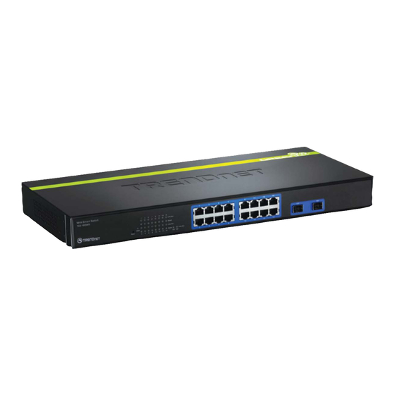
ABOUT THIS GUIDE Congratulations on your purchase of the 16-Port 10/100/1000Mbps Gigabit Ethernet Web Smart Switch. This device integrates 1000Mbps Gigabit Ethernet, 100Mbps Fast Ethernet and 10Mbps Ethernet network capabilities in a highly flexible package. Purpose This guide discusses how to install your 16-Port 10/100/1000Mbps Gigabit Ethernet Web Smart Switch. -
Page 9: Introduction
INTRODUCTION This chapter describes the features of the 16-Port 10/100/1000Mbps Gigabit Ethernet Web Smart Switch and some background information about Ethernet/Fast Ethernet/Gigabit Ethernet switching technology. Gigabit Ethernet Technology Gigabit Ethernet is an extension of IEEE 802.3 Ethernet utilizing the same packet structure, format, and support for CSMA/CD protocol, full duplex, flow control, and management objects, but with a tenfold increase in theoretical throughput over 100-Mbps Fast Ethernet and a hundredfold increase over 10-Mbps Ethernet. -
Page 10: Fast Ethernet Technology
In addition, the phenomenal bandwidth delivered by Gigabit Ethernet is the most cost-effective method to take advantage of today and tomorrow’s rapidly improving switching and routing internetworking technologies. And with expected advances in the coming years in silicon technology and digital signal processing that will enable Gigabit Ethernet to eventually operate over unshielded twisted-pair (UTP) cabling, outfitting your network with a powerful 1000-Mbps- capable backbone/server connection creates a flexible foundation for... -
Page 11: Switching Technology
Switching Technology Another approach to pushing beyond the limits of Ethernet technology is the development of switching technology. A switch bridges Ethernet packets at the MAC address level of the Ethernet protocol transmitting among connected Ethernet or Fast Ethernet LAN segments. -
Page 12: Vlan (Virtual Local Area Network)
VLAN (Virtual Local Area Network) A VLAN is a group of end-stations that are not constrained by their physical location and can communicate as if a common broadcast domain, a LAN. The primary utility of using VLAN is to reduce latency and need for routers, using faster switching instead. - Page 13 512KBytes packet buffer Supports IEEE 802.3x flow control for full-duplex mode ports Supports Port-base VLAN Supports Port-base QoS Supports Trunk. Supports Port-mirroring Supports Port-setting for Speed/Disable, Flow control Easy configuration via WEB Browser Easy setting via Web Management Utility Standard 19” Rack-mount size...
-
Page 15: Unpacking And Installation
UNPACKING AND INSTALLATION This chapter provides unpacking and installation information for the Switch. Unpacking Open the shipping cartons of the Switch and carefully unpacks its contents. The carton should contain the following items: 16-Port 10/100/1000Mbps Gigabit Web-Smart Switch Multi-Language Quick Installation Guide CD-ROM (User’s Guide &... -
Page 16: Rack Mounting
Leave at least 10cm of space at the front and rear of the hub for ventilation. Install the Switch on a sturdy, level surface that can support its weight, or in an EIA standard-size equipment rack. For information on rack installation, see the next section, Rack Mounting. -
Page 17: Connecting Network Cable
Figure 2. Combine the Switch with the provided screws Then, use screws provided with the equipment rack to mount each switch in the rack. Figure 3. Mount the Switch in the rack Connecting Network Cable The Switch supports 1000Mbps Gigabit Ethernet that runs in Auto- negotiation mode and 10Mbps Ethernet or 100Mbps Fast Ethernet that runs both in half and full duplex mode and 1000Mbps Gigabit Ethernet runs in full duplex mode using four pair of Category 5 Cable. -
Page 18: Ac Power
AC Power The Switch used the AC power supply 100-240V AC, 50-60 Hz. The power switch is located at the rear of the unit adjacent to the AC power connector and the system fan. The switch’s power supply will adjust to the local power source automatically and may be turned on without having any or all LAN segment cables connected. -
Page 19: Identifying External Components
IDENTIFYING EXTERNAL COMPONENTS This chapter describes the front panel, rear panel, and LED indicators of the Switch. Front Panel The figure below shows the front panels of the Switch. Figure 4. Front panel of 16-port Gigabit Ethernet Switch LED Indicator: Comprehensive LED indicators display the status of the switch and the network (see the LED Indicators chapter below). -
Page 20: Rear Panel
Rear Panel Figure 5. Rear panel of the Switch AC Power Connector: This is a three-pronged connector that supports the power cord. Plug in the female connector of the provided power cord into this connector, and the male into a power outlet. Supported input voltages range from 100-240V AC at 50-60Hz. -
Page 21: Understanding Led Indicators
UNDERSTANDING LED INDICATORS The front panel LEDs provides instant status feedback, and, helps monitor and troubleshoot when needed. Figure 6. LED indicators of the Switch Power and System LEDs POWER: Power Indicator : When the Power LED lights on, the Switch is receiving power. : When the Power turns off or the power cord has improper connection. -
Page 22: Ports 1~16 Status Leds
Ports 1~16 Status LEDs Link/ACT: Link/Activity When the Link/ACT LED lights on, the respective port is successfully connected to an Ethernet network. Blinking When the Link/ACT LED is blinking, the port is transmitting or receiving data on the Ethernet network. No link. -
Page 23: Configuration
CONFIGURATION Through the Web Browser you can configure the Switch such as VLAN, Trunking, QoS… etc. With the attached Web Management Utility, you can easily discover all the Web Management Switch, assign the IP Address, changing the password and upgrading the new firmware. Installing the Web Management Utility The following gives instructions guiding you through the installations of the Web Management utility. -
Page 24: Discovery List
Figure 7. Web Management Utility The Web Management Utility was divided into four parts, Discovery List, Monitor List, Device Setting and Toolbar function, for details instruction, follow the below section. Discovery List This is the list where you can discover all the Web management devices in the entire network. -
Page 25: Monitor List
System word definitions in the Discovery List: MAC Address: Shows the device MAC Address. IP Address: Shows the current IP address of the device. Protocol version: Shows the version of the Utility protocol. Product Name: Shows the device product name. System Name: Shows the appointed device system name. - Page 26 View Trap: The Trap function can receive the events that happen from the Web Management Switch in the Monitor List. There is a light indicator behind the “View Trap” button, when the light indicates in green, it means that there is no trap transmitted, and else when it indicates in red, it means that there is new trap transmitted, this is to remind us to view the trap.
-
Page 27: Device Setting
Device Setting You can set the device by using the function key in the Device Setting Dialog box. Configuration Setting: In this Configuration Setting, you can set the IP Address, Subnet Mask, Gateway, Set Trap to (Trap IP Address), System name and Location. Select the device in the Discovery list or Monitor List and press this button, then the Configuration Setting window will pop out as Figure 10, after filling up the data that you want to change, you must fill up... - Page 28 Password Change: You can use this Password Change when you need to change the password, fill in the password needed in the dialog box and press “Set” button to proceed the password change immediately. Figure 11. Password Change Firmware Upgrade: When the device has a new function, there will be a new firmware to update the device, use this function to update.
-
Page 29: Toolbar
Toolbar The toolbar in the Web Management Utility have four main tabs, File, View, Options and Help. In the “File TAB”, there are Monitor Save, Monitor Save As, Monitor Load and Exit. Monitor Save: To record the setting of the Monitor List to the default, when you open the Web Management Utility next time, it will auto load the default recorded setting. -
Page 30: Configuring The Switch
Configuring the Switch The 16-Port 10/100/1000Mbps Gigabit Ethernet Web Smart Switch has a Web GUI interface for smart switch configuration. The Switch can be configured through the Web Browser. A network administrator can manage, control and monitor the switch from the local LAN. This section indicates how to configure the Switch to enable its smart functions including: Port Setting (Speed/Disable, Duplex mode, Flow Control and... - Page 31 Open Internet Explorer 5.0 or above Web browser. Enter IP address http://192.168.0.1 (the factory-default IP address setting) to the address location. Figure 13. Or through the Web Management Utility, you do not need to remember the IP Address, select the device shown in the Monitor List of the Web Management Utility to settle the device on the Web Browser.
-
Page 32: Setup Menu
After entering the password, the main page comes up, the screen will display the device status. Figure 15. Device Status Setup Menu When the main page appears, find the Setup menu in the left side of the screen (Figure 16). Click on the setup item that you want to configure. -
Page 33: Configuring Setup Setting
Figure 16. Setup menu Configuring Setup Setting Find that there are four items, including Port Settings, VLAN Settings, Trunk Settings and Mirror Settings in Setup menu. Port Settings In Port Settings menu (Figure 17), this page will show each port’s status, press the ID parameter to set each port’s Speed, Flow Control, QoS priority and Link Status. - Page 34 The Link Status in the screen will show the connection speed and duplex mode; else this dialog box will show down when the port is disconnected. Figure 17. Port Setting To change the port setting, click on the ID parameter to enter to the selected port to configure its Speed/Disable, Flow control and QoS setting.
-
Page 35: Vlan Settings (Virtual Local Area Network)
Speed/Disable: This setting has six modes—100M Full, 100M Half, 10M Full, 10M Half, Auto and Disable—for speed or port disable selections. Flow Control: This setting determines whether or not the Switch will be handling flow control. Set Flow Control to Enable for avoiding data transfer overflow. -
Page 36: Trunk Setting
Once you want to modify the VLAN Group, check on the ID parameter, the ID VLAN configuration window will pop out. Figure 20. VLAN Settings Trunk Setting The Trunk function enables to cascade two devices with a double times bandwidth (maximum up to 16Gbps in full duplex mode). There are three selections in each group of trunk setting as follow: Group 1: Selection 1(disable), Selection 2(port 1, 2), Selection 3(port 1, 2, 3, 4). -
Page 37: Mirror Setting
Mirror Setting Port Mirroring is a method of monitoring network traffic that forwards a copy of each incoming and/or outgoing packet from one port of a network switch to another port where the packet can be studied. It enables the manager to keep close track of switch performance and alter it if necessary. -
Page 38: Device Status
Device Status Click on the “Status” to present the device status on this screen, it will show the System Status, Port Status, VLAN Status, Trunk Status and Mirror Status.. Press “Refresh” when you need to renew the posted information. -
Page 39: Statistic
Statistic The Statistic Menu screen will show the status of each port packet count. Figure 23. Statistic For Detail packet information, click on the ID parameter as Figure 24. Figure 24. -
Page 40: System Setting
System Setting The System Setting includes the System name, Location name, Login Timeout, IP Address, Subnet Mask and Gateway. Through the Web Management Utility, you can easily recognize the device by using the System Name and the Location Name. The Login Timeout is to set the idle time-out for security issue, when there is no action in running the Web Smart Utility and the time is up, you must re-login to Web Smart Utility before you set the Utility. -
Page 41: Trap Setting
Trap Setting The Trap Setting enables the device to monitor the Trap through the Web Management Utility, set the Trap IP Address of the manager where the trap to be sent. Figure 26. Trap Setting System Events: Monitoring the system’s trap. Device Bootup: a trap when booting up the system. -
Page 42: Backup Setting
Backup Setting The backup tools help you to backup the current setting of the Switch. Once you need to backup the setting, press the “Backup” button to save the setting. To restore a current setting file to the device, you must specify the backup file and press “Restore”... -
Page 43: Logout
Logout When press this function, the web configuration will go back to first Login page. Figure 30. Logout... -
Page 45: Technical Specifications
TECHNICAL SPECIFICATIONS General Standards IEEE 802.3 10BASE-T Ethernet IEEE 802.3u 100BASE-TX Fast Ethernet IEEE 802.3ab 1000BASE-T Gigabit Ethernet IEEE 802.3x Full Duplex Flow Control Protocol CSMA/CD Data Ethernet: 10Mbps (half duplex), 20Mbps (full-duplex) Transfer Rate Fast Ethernet: 100Mbps (half duplex), 200Mbps (full- duplex) Gigabit Ethernet: 2000Mbps (full-duplex) Topology... - Page 46 Performance Transmits Method: Store-and-forward Filtering Address 8K entries per device Table: Packet 10Mbps Ethernet: 14,880/pps Filtering/Forwarding 100Mbps Fast Ethernet: 148,800/pps Rate: 1000Mbps Gigabit Ethernet: 1,488,000/pps Address Automatic update Learning: Transmits Method: Store-and-forward RAM Buffer: 512KBytes per device...
- Page 47 TEG-160WS – 5 Years Warranty If a product does not operate as warranted above during the applicable warranty period, TRENDware shall, at its option and...
- Page 48 (iii) the product was subject to conditions more severe than those specified in the manual. Warranty service may be obtained by contacting TRENDware office within the applicable warranty period for a Return Material Authorization (RMA) number, accompanied by a copy of the dated proof of the purchase.
- Page 49 PERSON’S MISUSE, NEGLECT, IMPROPER INSTALLATION OR TESTING, UNAUTHORIZED ATTEMPTS TO REPAIR OR MODIFY, OR ANY OTHER CAUSE BEYOND THE RANGE OF THE INTENDED USE, OR BY ACCIDENT, FIRE, LIGHTNING, OR OTHER HAZARD. LIMITATION LIABILITY: FULL EXTENT ALLOWED BY LAW TRENDWARE ALSO EXCLUDES FOR ITSELF AND ITS SUPPLIERS ANY LIABILITY, WHETHER BASED CONTRACT...
- Page 50 TRENDware website. TRENDware provides FREE technical support for all customers for the duration of the warranty period on this product. TRENDware Technical Support Tel: +1-310-626-6252 Fax: +1-310-626-6267 E-mail: support@trendware.com www.TRENDnet.com Monday ~ Friday, 7:30AM ~ 6:00PM Pacific Standard Time (Except holidays)
Need help?
Do you have a question about the TEG-160WS and is the answer not in the manual?
Questions and answers