Advertisement
Quick Links
Advertisement

Related Manuals for Pass Laboratories Pass X5


Summary of Contents for Pass Laboratories Pass X5
- Page 1 Pass X5 Owner's Manual Page 1...
- Page 2 Now For Something Completely Different: The X5 five channel amplifier embodies the design technology and refinements of the larger "X" series amplifiers including extensions of the patented Supersymmetry circuit. The Supersymmetry circuit topology was granted a U.S. patent in 1994, and is the result of 19 years of effort by Nelson Pass.
- Page 3 Setup You can position the amplifier anywhere you want, but it requires ventilation. We do not recommend placing it in enclosed cabinets or small closets without means for air to circulate freely. The amplifier idles at about 200 watts. Let’s talk about power requirements. The amplifier draws about 2 amps (continuous rms) out of the wall during normal audio operation, and this reflects mostly the idle current that we run through the output stage.
- Page 4 amplifiers is almost non-existent. This is small comfort to the few, but take it easy and give us a call if you have problems. People are interested in how long it takes for these amplifiers to break in. It takes about an hour for them to warm up, and this is where we adjust them first.
- Page 5 Interconnects and Speaker Cables We have a general recommendation about interconnects, which is that they should cost less than the amplifier. We have tried a lot of products and most of them work well, but as a practical matter we cannot make blanket recommendations. The amplifier is not sensitive to source interconnects.
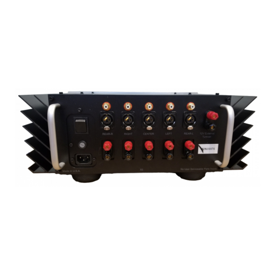
- Page 6 The X5 has 40 output Mosfet power transistors in TO-3 plastic packages, again matched to 0.5% and drawn from the same lot codes for each type. The output stages can sustain transients of about 1,000 watts per channel, but are not allowed to dissipate more than half that, even into a dead short.
- Page 7 Supersymmetry: What it is, Where it came from, How it works, Why bother ( theory and philosophy by Pass that you can ignore ) Supersymmetry is the name given to a new type of amplifying circuit, which operates quite differently than the designs presently appearing in literature and the marketplace. I have been designing new amplifiers all my adult life, and patented several of them, but I regard this particular idea as the most interesting and profound.
- Page 8 “local feedback” are still considered “no feedback”. Anybody disagreeing with this should send me a diagram of a “true no feedback” circuit, and I will try to point out the hidden feedback. On the push-pull front, a major improvement was offered by Class A operation, not a new concept, which delivered significantly better performance by sending a much larger amount of current idling through the gain devices.
- Page 9 Supersymmetry is not a single pencil stroke, but I am making progress. Its origin goes back to the late 1970’s when I was examining the virtues and faults of so-called “error correcting amplifiers”, an alternative to conventional feedback. In this approach, two amplifiers, a big one and a small one work together.
- Page 10 without compensation. In fact, if you build a supersymmetric circuit with multiple gain stages, it does not work as well. In 1993 I attempted to build the first power amplifier using this principle, but it was not successful. Ironically, the supersymmetric concept not only allows for very simple gain circuits, but it requires them for good performance.
- Page 11 The supersymmetric amplifier is a special subset of balanced amplifiers, unique and covered by U.S. patent. Supersymmetry is an approach that truly takes advantage of balanced operation like no other and requires a balanced input to retain the precisely matched behavior. Supersymmetry is ideally used to obtain high quality performance from very simple circuit topologies, avoiding the high order distortion character and feedback instabilities of complex circuits.
- Page 12 On this curve (B) we can clearly see that intrinsic symmetry due to the matching of the two halves reduces the distortion by a factor of 10. Supersymmetry (D) creates a more perfect match, and results in an additional reduction by a factor of 10. However there is essentially no difference in the distortion figures at the output (C) of each half of the circuit considered alone.
- Page 13 X5 SPECIFICATIONS All figures obtained after 1 hour warmup, with regulated 120 VAC power line. See manual notes about AC power line regulation. Gain 30 dB Freq. Response -0 dB at DC, -3 dB at 100 kHz Power Output 125 X 5 watts maximum @ 1% THD, 1 kHz, 8 ohms Distortion refer to accompanying distortion curve Maximum Output Voltage...
Need help?
Do you have a question about the Pass X5 and is the answer not in the manual?
Questions and answers