Table of Contents
Advertisement
Quick Links
Advertisement
Table of Contents

Subscribe to Our Youtube Channel
Related Manuals for Fantom Drives MGT-08SC08A


Summary of Contents for Fantom Drives MGT-08SC08A
- Page 1 RAID SCSI TO S-ATA Installation Reference Guide Revision 1.0 P/N: PW0020000000315...
- Page 2 Copyright No part of this publication may be reproduced, stored in a retrieval system, or transmitted in any form or by any means, electronic, mechanical, photocopying, recording or otherwise, without the prior written consent. Trademarks All products and trade names used in this document are trademarks or regis- tered trademarks of their respective holders.
- Page 3 FCC Compliance Statement This equipment has been tested and found to comply with the limits for a Class B digital device, pursuant to Part 15 of the FCC rules. These limits are designed to provide reasonable protection against harmful interference in residential installations.
-
Page 4: About This Manual
About This Manual Welcome to your Redundant Array of Independent Disks System User’s Guide. This manual covers everything you need to know in learning how to install or configure your RAID system. This manual also assumes that you know the basic concepts of RAID technology. -
Page 5: Table Of Contents
Table of Contents Chapter 1 Introduction Key Features... RAID Concepts... SCSI Concepts... 1.3.1 Multiple SCSI Format Support... 1.3.2 Host SCSI ID Selection... 1.3.3 Terminators... Array Definition... 1.4.1 RAID set... 1.4.2 Volume Set... 1.4.3 Easy of Use features... 1.4.4 High Availability... Chapter 2 Getting Started Unpacking the subsystem... - Page 6 3.6.7 Delete Hot Spare... 3.6.8 Rescue Raid Set... Volume Set Function... 3.7.1 Create Volume Set... 3.7.2 Delete Volume Set... 3.7.3 Modify Volume Set... 3.7.3.1 Volume Expansion... 3.7.4 Volume Set Migration... 3.7.5 Check Volume Set... 3.7.6 Stop Volume Set Check... Physical Drive... 3.8.1 Create Pass-Through Disk...
-
Page 7: Chapter 1 Introduction
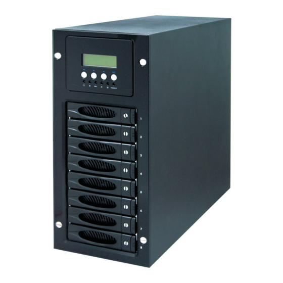
Chapter 1 Introduction The RAID subsystem is a Ultra 320 LVD SCSI-to-Serial ATA II RAID (Redundant Arrays of Independent Disks) disk array subsystem. It consists of a RAID disk array controller and eight (8) disk trays. The subsystem is a “Host Independent” RAID subsystem supporting RAID lev- els 0, 1, 3, 5, 6 0+1 and JBOD. -
Page 8: Key Features
1.1 Key Features Subsystem Features: Features an Intel 80321 64 bit RISC I/O processor Build-in 128MB cache memory, expandable up to 1024MB Ultra 320 LVD host port Supports up to eight (8) 1" hot-swappable Serial ATA II hard drives High quality advanced cooling fans Local audible event notification alarm Supports password protection and UPS connection Built-in R-Link LAN port interface for remote management &... -
Page 9: Raid Concepts
Disk Striping Fundamental to RAID technology is striping. This is a method of combining multiple drives into one logical storage unit. Striping partitions the storage space of each drive into stripes, which can be as small as one sector (512 bytes) or as large as several megabytes. - Page 10 RAID 0 arrays deliver the best data storage efficiency and performance of any array type. The disadvantage is that if one drive in a RAID 0 array fails, the entire array fails.
- Page 11 RAID 1 , also known as disk mirroring, is simply a pair of disk drives that store duplicate data but appear to the computer as a single drive. Although striping is not used within a single mirrored drive pair, multiple RAID 1 arrays can be striped together to create a single large array consisting of pairs of mirrored drives.
- Page 12 RAID 3 sector-stripes data across groups of drives, but one drive in the group is dedicated to storing parity information. RAID 3 relies on the embedded ECC in each sector for error detection. In the case of drive failure, data recovery is accomplished by calculating the exclusive OR (XOR) of the information recorded on the remaining drives.
- Page 13 RAID 6 is similar to RAID 5 in that data protection is achieved by writing parity information to the physical drives in the array. With RAID 6, however, two sets of parity data are used. These two sets are different, and each set occupies a capacity equivalent to that of one of the constituent drives.
- Page 14 RAID 5 with a small stripe size offers similar performance. RAID 5 combines efficient, fault-tolerant data storage with good performance characteristics. However, write performance and performance during drive failure is slower than with RAID 1. Rebuild operations also require more time than with RAID 1 because parity information is also reconstructed.
-
Page 15: Raid Management
RAID Management The subsystem can implement several different levels of RAID technology. RAID levels supported by the subsystem are shown below. RAID Level Block striping is provide, which yields higher performance than with individual drives. There is no redundancy. Drives are paired and mirrored. All data is 100% duplicated on an equivalent drive. -
Page 16: Scsi Concepts
1.3 SCSI Concepts Before configuring the subsystem, you must first understand some basic SCSI concepts so that the subsystem and SCSI devices will function properly. 1.3.1 Multiple SCSI Format Support The subsystem support the SCSI interface standards listed below. Note that the data bit and cable length restrictions must be followed. -
Page 17: Terminators
1.3.3 Terminators Based on SCSI specifications, the SCSI bus must be terminated at both ends, meaning the devices that are connected to the ends of the SCSI bus must have their bus terminators enabled. Devices connected in the middle of the SCSI bus must have their terminators disabled. -
Page 18: Array Definition
1.4 Array Definition 1.4.1 RAID Set A RAID Set is a group of disks containing one or more volume sets. It is impossible to have multiple RAID Sets on the same disks. A Volume Set must be created either on an existing RAID set or on a group of available individual disks (disks that are not yet a part of an raid set). -
Page 19: Easy Of Use Features
1.4.3 Easy of Use features 1.4.3.1 Instant Availability/Background Initialization RAID 0 and RAID 1 volume set can be used immediately after the creation. But the RAID 3, 5 and 6 volume sets must be initialized to generate the parity. In the Normal Initialization, the initialization proceeds as a background task, the volume set is fully accessible for system reads and writes. - Page 20 1.4.3.3 Online Capacity Expansion Online Capacity Expansion makes it possible to add one or more physical drive to a volume set, while the server is in operation, eliminating the need to store and restore after reconfiguring the raid set. When disks are added to a raid set, unused capacity is added to the end of the raid set.
-
Page 21: High Availability
1.4.3.4 Online RAID Level and Stripe Size Migration User can migrate both the RAID level and stripe size of an existing volume set, while the server is online and the volume set is in use. Online RAID level/ stripe size migration can prove helpful during performance tuning activities as well as in the event that additional physical disks are added to the RAID subsystem. - Page 22 1.4.4.2 Hot-Swap Disk Drive Support The RAID subsystem has built the protection circuit to support the replace- ment of UDMA hard disk drives without having to shut down or reboot the system. The removable hard drive tray can deliver “hot swappable,” fault- tolerant RAID solutions at prices much less than the cost of conventional SCSI hard disk RAID subsystems.
-
Page 23: Chapter 2 Getting Started
Chapter 2 Getting Started Getting started with the subsystem consists of the following steps: Unpack the storage subsystem. Identifying Parts of the subsystem. Connecting to Host. SCSI Termination. Power on the subsystem. Install Hard Drives. 2.1 Unpacking the Subsystem Before continuing, first unpack the subsystem and verify that the contents of the shipping carton are all there and in good condition. - Page 24 move the components; contact the dealer where the subsystem was purchased for further instructions. The package contains the following items: • RAID subsystem unit • One power cord • Two external SCSI cables • One external null modem cable • One RJ-45 ethernet cable •...
-
Page 25: Identifying Parts Of The Subsystem
2.2 Identifying Parts of the subsystem The illustrations below identify the various features of the subsystem. Get yourself familiar with these terms as it will help you when you read further in the following sections. 2.2.1 Front View 1. LCD display panel 2. - Page 26 3. Environment status Parts If temperature irregularity in these systems occurs (HDD slot tem- Disk Fault & Warning LED perature over 60 will sound. Power LED Green LED indicates power is on. Access LED Blue blinking LED indicates data is being accessed. 4.
-
Page 27: Rear View
2.2.2 Rear View HOST A HOST B R LINK Monitor Power Input Socket 1. Host Channel A & B The subsystem is equipped with 2 host channels (Host channel A and Host channel B). The host channel with two 68-pin SCSI connectors at the rear of the subsystem for SCSI in and out. -
Page 28: Connecting To Host
3. Monitor Port The subsystem is equipped with a serial monitor port allowing you to connect a PC or terminal. 4. Cooling Fan module Two fans are located at the rear of the subsystem. They provide sufficient airflow and heat dispersion inside the chassis. 5. - Page 29 HOST A in HOST B in Note: 1. When one or more SCSI devices are connected, the total length of all cables (internal or external) must not exceed 3 meters (9.8 ft.) to ensure reliable operation. 2. For safety reasons, make sure the Disk Array and Host Computer are turned off when you plug-in the SCSI cable.
-
Page 30: Scsi Termination
2.4 SCSI Termination Two 68-pin wide SCSI connectors are provided on the back of the enclosure for connecting the array to the system. These connectors are used in one of two ways: If the disk array is the only external SCSI device, or is the last external device in a daisy-chained configuration, connect the incoming cable (the one which is attached to the SCSI adapter) to the Host A &... - Page 31 Correct SCSI termination procedures require that the last devices on the SCSI bus be terminated. If the last device is not terminated, or if devices other than the last are terminated, erratic SCSI bus performance may occur. Typically, the system or host adapter (SCSI card inside the PC) is the first device and is already terminated.
-
Page 32: Powering-On The Subsystem
2.5 Powering-on the Subsystem When you connect the Disk Array to the Host computer, you should press the ON/OFF Power Supply Switch. It will turn the Disk Array on and the Self-Test will be started automatically. Plug in the power cord or power connector located at the rear of the subsystem. -
Page 33: Install Hard Drives
2.6 Install Hard Drives This section describes the physical locations of the hard drives supported by the subsystem and gives instructions on installing a hard drive. The subsystem supports hot-swapping allowing you to install or replace a hard drive while the subsystem is running. - Page 34 Note: When removing the Drive Tray Module from the enclosure, handle with care to prevent dropping the module. To install the hard drive into the Drive Tray, first insert the hard drive as show below. Turn the Drive Tray over. Notice the 4 screws. Tighten these 4 screws to firmly secure the hard drive to the Drive Tray.
-
Page 35: Chapter 3 Configuring
Chapter 3 RAID Configuring The subsystem has a setup configuration utility built in containing important information about the configuration as well as settings for various optional func- tions in the subsystem. This chapter explains how to use and make changes to the setup utility. - Page 36 terminal emulation mode to the monitor port located at the rear of the subsystem. Note: You may connect a terminal while the subsystem’s power is on. Power-on the terminal. Run the VT100 program or an equivalent terminal program. RAID Configuring...
- Page 37 The default setting of the monitor port is 115200 baud rate, 8 data bit, non-parity, 1 stop bit and no flow control. RAID Configuring...
- Page 38 Click disconnect button. Open the File menu, and then open Properties. RAID Configuring...
- Page 39 Open the Settings Tab. Open the Settings Tab. Function, arrow and ctrl keys act as: Terminal Keys, Backspace key sends: Crtl+H, Emulation: VT100, Telnet terminal: VT100, Back scroll buffer lines: 500. Click OK. RAID Configuring...
- Page 40 Now, the VT100 is ready to use. After you have finished the VT100 Termi- nal setup, you may press “ X “ key (in your Terminal) to link the RAID subsystem and Terminal together. Press “X’ key to display the disk array Monitor Utility screen on your VT100 Terminal.
- Page 41 Main Menu The main menu shows all function that enables the customer to execute actions by clicking on the appropriate link. Note: The password option allows user to set or clear the raid subsystem’s password protection feature. Once the password has been set, the user can only monitor and configure the raid subsystem by providing the cor- rect password.
- Page 42 VT100 terminal configuration Utility Main Menu Options Select an option and the related information or submenu items display beneath it. The submenus for each item are explained on the section 3.3. The configu- ration utility main menu options are: Option Quick Volume And Raid Set Setup Raid Set Functions...
-
Page 43: Configuring The Subsystem Using The Lcd Panel
3.2 Configuring the Subsystem Using the LCD Panel The LCD Display front panel function keys are the primary user interface for the Disk Array. Except for the “Firmware update” ,all configuration can be per- formed through this interface.The LCD provides a system of screens with ar- eas for information, status indication, or menus. -
Page 44: Menu Diagram
3.3 Menu Diagram The following tree diagram is a summary of the various configuration and set- ting functions that can be accessed through the LCD panel menus or the termi- nal monitor. Quick Volume / Raid Setup 3-10 Raid 0 Greater Two TB Volume Support Selected Capacity Select Stripe Size... - Page 45 Create Raid Set Delete Raid Set Expand Raid Set Raid Set Function Offline Raid Set Activate Raid Set Create Hot Spare Disk Delete Hot Spare Disk Raid Set Information Select IDE Drives for Raid Set Create Raid Set Edit The Raid Set Name Select Raid Set To Delete Delete Raid Set Are you sure?
- Page 46 Volume Set Function 3-12 Create Volume Set Create Volume From Raid Set Volume Creation Create Volume Initialization Mode Delete Volume Set Delete Volume From Raid Set Select Volume To Delete Delete Volume Set Are you sure? Modify Volume Set Modify Volume From Raid Set Select Volume To Modify Volume Modification Modify Volume...
- Page 47 Physical Drives Raid System Function View Drive Information Select The Drives Create Pass Through Disk Select The Drives Modify Pass Through Disk Select The Drives Delete Pass Through Disk Select The Drives Delete Pass Through Are you sure? Identify Selected Drive Select The Drives Yes, No Mute The Alert Beeper...
- Page 48 U320 SCSI Target Config Ethernet Configuration View System Events Clear Event Buffer Hardware Monitor System Information 3-14 Channel 0 QAS Enabled, Disabled Channel 1 QAS Enabled, Disabled Auto Speed Down Enabled, Disabled Two TB CDB Select 12 Bytes CDB, 16Bytes CDB Inband SCSI Function Enabled, Disabled Inband SCSI Channel...
-
Page 49: Web Browser-Based Remote Raid Management Via R-Link Ethernet
3.4 Web browser-based Remote RAID management via R-Link ethernet port Configuration of the internal RAID subsystem with remote RAID management is a web browser-based application, which utilizes the browser installed on your oper- ating system. Web browser-based remote RAID management can be used to man- age all the raid function. - Page 50 Main Menu The main menu shows all function that enables the customer to execute actions by clicking on the appropriate link. Individual Category Quick Create Raid Set Functions Volume Set Functions Physical Drive System Control Information 3-16 Description Create a RAID configuration, which is consist of the number of physical disk installed;...
-
Page 51: Quick Create
Configuration Procedures Below are a few practical examples of concrete configuration procedures. 3.5 Quick Create The number of physical drives in the raid subsystem determines the RAID levels that can be implemented with the raid set. You can create a raid set associated with exactly one volume set. - Page 52 Greater Two TB Volume Support: No: still keep the volume size with max. 2TB limitation. 64bit LBA: the max. size 512TB, for Unix or Linux. Due to LSI53C1030T does not support 16byte CDB for 64bit LBA, vendor specific 12byte CDB is used for 64bit LBA support. The system may detect up to two tera bytes only.
-
Page 53: Raid Set Functions
3.6 Raid Set Functions Use the Raid Set Function and Volume Set Function if you prefer to customize your system. User manual configuration can full control of the raid set setting, but it will take longer to complete than the Quick Volume/Raid Setup configuration. -
Page 54: Delete Raid Set
3.6.2 Delete Raid Set To delete a raid set, click on the Delete Raid Set link. A “Select The RAID SET To Delete” screen is displayed showing all raid set existing in the current controller. Click the raid set number you which to delete in the select column to delete screen. Tick on the Confirm The Operation and click on the Submit button in the screen to delete it. -
Page 55: Expand Raid Set
3.6.3 Expand Raid Set Use this option to expand a raid set, when a disk is added to your system. This function is active when at least one drive is available. To expand a raid set, click on the Expand Raid Set link. Select the target raid set, which you want to expand it. - Page 56 Migrating occurs when a disk is added to a raid set. Migration status is dis- played in the raid status area of the Raid Set information when a disk is added to a raid set. Migrating status is also displayed in the associated volume status area of the volume set Information when a disk is added to a raid set.
-
Page 57: Offline Raid Set
3.6.4 Offline Raid Set If user wants to move the Raid Set, when the RAID subsystem is power on. User can use the Offline Raid Set option to offline the raid set. After user complete the function, the HDD State will change to offline Mode. To offline a raid set, click on the Offline Raid Set link. - Page 58 RAID Configuring 3-24...
- Page 59 RAID Configuring 3-25...
-
Page 60: Create Hot Spare
3.6.6 Create Hot Spare When you choose the Create Hot Spare option in the Raid Set Function, all unused physical devices connected to the current controller appear: Select the target disk by clicking on the appropriate check box. Tick on the Confirm The Operation, and click on the Submit button in the screen to create the hot spares. -
Page 61: Delete Hot Spare
3.6.7 Delete Hot Spare Select the target Hot Spare disk to delete by clicking on the appropriate check box. Tick on the Confirm The Operation, and click on the Submit button in the screen to delete the hot spares. 3.6.8 Rescue Raid Set If you try to Rescue Missing RAID Set, please contact our engineer for assistance. -
Page 62: Volume Set Function
3.7 Volume Set Function A volume set is seen by the host system as a single logical device. It is orga- nized in a RAID level with one or more physical disks. RAID level refers to the level of data performance and protection of a volume set. A volume set ca- pacity can consume all or a portion of the disk capacity available in a raid set. - Page 63 Volume Name: The default volume name will always appear as Volume Set. #. You can re- name the volume set name providing it does not exceed the 16 characters limit. Raid Level: Set the RAID level for the Volume Set. Highlight Raid Level and press Enter. The available RAID levels for the current Volume Set are displayed.
- Page 64 to two tera bytes only. A patch driver is needed to enable the system to detect over two tera bytes. Please contact your vendor for supporting. 4K Block: the max. size 16TB , just use with “ basic disk manager “ under OS Window 2000, 2003 or XP.
-
Page 65: Delete Volume Set
SCSI ID: Each SCSI device attached to the SCSI card, as well as the card itself, must be assigned a unique SCSI ID number. A Wide SCSI channel can connect up to 15 devices. The RAID subsystem is as a large SCSI device. We should assign an ID from a list of SCSI IDs. -
Page 66: Modify Volume Set
3.7.3 Modify Volume Set To modify a volume set from a raid set: (1). Click on the Modify Volume Set link. (2). Tick on the volume set from the list that you wish to modify. Click on the Submit button. The following screen appears. - Page 67 RAID Configuring 3-33...
-
Page 68: Volume Set Migration
3.7.4 Volume Set Migration Migrating occurs when a volume set is migrating from one RAID level to another, a volume set strip size changes, or when a disk is added to a raid set. Migration status is displayed in the volume status area of the RaidSet Hierarchy screen when one RAID level to another, a Volume set strip size changes or when a disk is added to a raid set. -
Page 69: Check Volume Set
3.7.5 Check Volume Set Use this function to perform Volume Set consistency check, which verifies the correctness of redundant data (data blocks and parity blocks) in a Volume Set. This basically means computing the parity from the data blocks and comparing the results to the contents of the parity blocks, or computing the data from the parity blocks and comparing the results to the contents of the data blocks. -
Page 70: Stop Volumeset Check
NOTE: When the 2 options are not selected, it will only check for errors. It is recommended to perform Check Volume Set with the 2 options unselected at first. If the result shows error, the two options can be selected and redo Check Volume Set to correct the errors. -
Page 71: Physical Drive
3.8 Physical Drive Choose this option from the Main Menu to select a physical disk and to per- form the operations listed below. 3.8.1 Create Pass-Through Disk To create pass-through disk, move the mouse cursor to the main menu and click on the Create Pass-Through link. -
Page 72: Modify Pass-Through Disk
3.8.2 Modify Pass-Through Disk Use this option to modify the Pass-Through Disk Attribute. User can modify the cache mode, Tagged Command Queuing, Max SCSI speed and SCSI channel/ID/LUN on an existed pass through disk. To modify the pass-through drive attribute from the pass-through drive pool, move the mouse cursor bar to click on Modify Pass-Through link. -
Page 73: Delete Pass-Through Disk
3.8.3 Delete Pass-Through Disk To delete pass-through drive from the pass-through drive pool, move the mouse cursor bar to the main menus and click on Delete Pass Through link. After you complete the selection, tick on the Confirm The Operation and click on the Submit button to complete the delete action. -
Page 74: System Configuration
3.9 System Configuration 3.9.1 System Configuration To set the raid system function, move the cursor bar to the main menu and click on he Raid System Function link. The Raid System Function menu will show all items. Select the desired function. System Beeper Setting: The Alert Beeper function item is used to Disabled or Enable the RAID sub- system controller alarm tone generator. - Page 75 Terminal Port Configuration: Speed setting values are 1200, 2400, 4800, 9600, 19200,38400, 57600, and 115200. Stop Bits values are 1 bit and 2 bits. Note: Parity value is fixed at None. Data Bits value is fixed at 8 bits. JBOD/RAID Configuration The RAID subsystem supports JBOD and RAID configuration.
- Page 76 ered up altogether at the same time. The power transfer time (lag time) from the last HDD to the next one can be set within the range of 0.4 to 6.0. Spin Down Idle HDD (Minutes): This option is to spin down hard drives after they have been idle for a select- able amount of time.
- Page 77 3.9.2 U320 SCSI Target Config To set the U320 SCSI Target function, move the cursor bar to the main menu and click on the U320 SCSI Target Config. Channel 0 / 1 QAS: The Enabled option supports Quick Arbitration and Selection (QAS). QAS re- duces the overhead of control release on the SCSI bus from one device to another.
-
Page 78: Ethernet Config
3.9.3 EtherNet Config To set the EtherNet function, move the cursor bar to the main menu and click on he EtherNet Config. The Raid System EtherNet Function menu will show all items. Select the desired function. 3.9.3.1 DHCP Host Name Support If DHCP Function is “Enabled”... -
Page 79: Alert By Mail Config
3.9.4 Alert By Mail Config To set the Event Notification function, move the cursor bar to the main menu and click on the Alert By Mail Config. The Raid System Event Notification Function menu will show all items. Select the desired function. When an abnormal condition occurs, an error message will be email to administrator that a problem has occurred. -
Page 80: Snmp Configuration
3.9.5 SNMP Configuration The SNMP gives users independence from the proprietary network management schemes of some manufacturers and SNMP is supported by many WAN and LAN manufacturers enabling true LAN/ WAN management integration. To set the SNMP function, move the cursor bar to the main menu and click on he SNMP Configuration. -
Page 81: Ntp Configuration
message. This allows user to easily define which RAID unit is having problem. Once this setting is done, alert by mail configuration will also work in the same way. SNMP Trap Notification Configurations: Select the desired function. After you complete the addition, tick on the Confirm The Operation and click on the Submit button to complete the action. -
Page 82: View Events
3.9.7 View Events To view the RAID subsystem controller’s information, move the mouse cursor to the main menu and click on the System Information link. The Raid Sub- system events Information screen appears. Choose this option to view the system events information: Timer, Device, Event type, Elapse Time and Errors. -
Page 83: Generate Test Events
3.9.8 Generate Test Events If you want to generate test events, move the cursor bar to the main menu and click on he Generate Test Events. Tick on the Confirm The Operation, and click on the Submit button in the screen to create the hot spares. Then click on the View Events/Mute Beeper to view the test event. -
Page 84: Clear Events Buffer
3.9.9 Clear Events Buffer Use this feature to clear the entire events buffer information. 3.9.10 Modify Password To set or change the RAID subsystem password, move the mouse cursor to Raid System Function screen, and click on the Change Password link. The Modify System Password screen appears. -
Page 85: Upgrade Firmware
The password option allows user to set or clear the raid subsystem’s password protection feature. Once the password has been set, the user can only monitor and configure the raid subsystem by providing the correct password. The password is used to protect the internal RAID subsystem from unautho- rized entry. -
Page 86: Information Menu
3.10 Information Menu 3.10.1 RaidSet Hierarchy Use this feature to view the internal raid subsystem current raid set, current volume set and physical disk configuration. 3.10.2 System Information To view the RAID subsystem controller’s information, move the mouse cursor to the main menu and click on the System Information link. -
Page 87: Hardware Monitor
3.10.3 Hardware Monitor To view the RAID subsystem controller’s hardware monitor information, move the mouse cursor to the main menu and click the Hardware Monitor link. The Hard- ware Information screen appears. NOTE: When no disk drive is installed in the disk slot, the disk temperature will show “—”. -
Page 88: Creating A New Raid Or Reconfiguring An Existing Raid
3.11 Creating a New RAID or Reconfiguring an Existing RAID You can configure raid sets and volume sets using Quick Create or Raid Set Functions/Volume Set Functions configuration method. Each configuration method requires a different level of user input. The general flow of operations for raid set and volume set configuration is: Step Action... -
Page 89: Upgrading The Firmware
3.12 Upgrading the Firmware Upgrading Flash Firmware Programming Utility Since the RAID subsystem controller features flash firmware, it is not neces- sary to change the hardware flash chip in order to upgrade the RAID firmware. The user can simply re-program the old firmware through the RS-232 port. - Page 90 Upgrading Firmware Through ANSI/VT-100 Terminal Emulation Get the new version firmware for your RAID subsystem controller. For Example, download the bin file from your OEM’s web site onto the c: 1. From the Main Menu, scroll down to “Raid System Function” 2.
- Page 91 4. Select “ZMODEM modem” under Protocol. ZMODEM as the file transfer protocol of your terminal emulation software. 5. Click Browse. Look in the location where the Firmware upgrade software is located. Select the File name: “xxxxxxx.BIN” and click open. 6. Click Send. Send the Firmware Binary to the controller RAID Configuring 3-57...
- Page 92 7. When the Firmware completes downloading, the confirmation screen appears. Press “Yes” to start program the flash ROM. 8. When the Flash programming starts, a bar indicator will show “ Start Updating Firmware. Please Wait:”. RAID Configuring 3-58...
- Page 93 9. The Firmware upgrade will take approximately thirty seconds to complete. 10. After the Firmware upgrade is complete, a bar indicator will show “ Firmware Has Been Updated Successfully”. NOTE: The user has to reconfigure all of the settings after the firmware upgrade is complete, because all of the settings will default to the original default values.
- Page 94 Upgrading Firmware Through Web Browser Management Get the new version firmware for your RAID subsystem controller. 1. To upgrade the RAID subsystem firmware, move the cursor to Upgrade Firmware link. The Upgrade The Raid System Firmware screen appears. 2. Click Browse. Look in the location where the Firmware upgrade software is located.
- Page 95 5. After the firmware upgrade is complete, a bar indicator will show “ Firmware Has Been Updated Successfully” RAID Configuring 3-61...
-
Page 96: Appendix A Technical Specification
Appendix A Technical Specification RAID processor RAID level Cache memory No. of channels (host+disk) Host bus interface Data transfer Disk interface Hot swap disk bays Hot swap power supply Cooling fan MAID Support Multiple RAID selection SMTP, SNMP Support Array Roaming Bad block auto-remapping Online RAID level migration Audible alarm...
Need help?
Do you have a question about the MGT-08SC08A and is the answer not in the manual?
Questions and answers