Table of Contents
Advertisement
Quick Links
- Data Brochure
Zone Control 368
Occupied
Power
UnOccupied
Heat Required
Optimum Start / Stop
24 hr. Timer
Timer Active
System Pump
70°F
(21°C)
12 hrs.
1
Zone 1 Lo stage
• Dial the desired duration
6
18
of the UnOccupied period.
2
Zone 2 Hi stage
• Press start button at the time of day
you want the UnOcc. period to begin.
Timer Active light turns on.
3
Zone 3 Lo stage
0
24
40
100
UnOccupied
(4)
(38)
4
Zone 4 Hi stage
Duration
UnOccupied
Start
0 = always Occupied
24 = always UnOccupied
R
Zone Control 368
N R T L / C
One & Two Stage
LR 58223
Output
System
Pump
Input
120 V (ac)
Power
Supply
70
70
Input
tekmar RTUs
or Indoor
Sensors
70
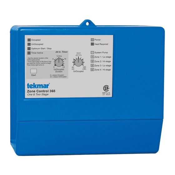
The Zone Control 368 is a microprocessor-based energy management control that uses PID
logic to control the temperature in up to 4 heating zones. Multiple zone controls can be
connected together for additional zones of heating. Either single stage or two stage zones can
be provided by the control. The 368 is primarily designed for use with the tekmar House
Controls. When connected to a House Control, the 368 provides indoor temperature feedback
that adjusts the supply water temperature in order to satisfy the zone with the highest heat
load. The 368 also coordinates the zoning operation in order to minimize boiler short cycling
and allow boiler purging between cycles. The 368 has a built in night setback timer and an
Optimum Start / Stop feature that allows the control to reheat the zones before the end of the
setback period.
Control Strategy . . . . . . . . . . . . . . . . pg. 2
Sequence of Operation . . . . . . . . . .
Installation . . . . . . . . . . . . . . . . . . . .
Settings . . . . . . . . . . . . . . . . . . . . . . . pg. 8
Occupied
UnOccupied
Optimum Start / Stop
24 hr. Timer
Timer Active
12 hrs.
• Dial the desired duration of the
6
18
UnOccupied period.
• Press start button at the time of day
you want the UnOcc. period to begin.
Timer Active light turns on.
0
24
40
UnOccupied
(4)
Duration
Start
0 = always Occupied
24 = always UnOccupied
Zone Control 368
One & Two Stage
Do not apply power here
1
2
3
4
5
6
System
Power
Com
RTU
RTU
Pmp
Pmp
N
L
Sen
1
T I M E
PRGM
1
2
AMPM
UNOCC
OVR
S
M
T
W T F
S
70
Input
tekmar
Timer
Power
Heat Required
System Pump
70°F
(21°C)
1
Zone 1 / Lo stage
2
Zone 2 / Hi stage
3
Zone 3 / Lo stage
100
(38)
4
Zone 4 / Hi stage
UnOccupied
Made in Canada by
tekmar Control Systems Ltd.
R
Power
N R T L / C
Pump Relay
LR 58223
Zone Relays
Caution: Signal wiring must be rated at least 300V
7
8
9 10 11
12 13 14
15
Com
RTU
RTU
UnO
Zo
Com
Zo
Com
2
Sen
3
4
Sw
Out
Sen
In
1-2
LR 58233 E150539
Output
tekmar Reset
Control
Testing the Control . . . pg. 9
pg. 3
Error Messages . . . . . . pg. 11
pg. 6
Technical Data . . . . . . . pg. 12
Limited Warranty . . . . . pg. 12
Thermal Motor
Optimum Start
Occ/UnOcc
Zone
1
2
3
4
Occ. only
Off
T est
Sep 96
31000266
120 V 50/60 Hz 5 VA
120 V (ac) 6 A 1/3 hp, pilot duty 240 VA
120 V (ac) 6 A 1/3 hp, pilot duty 240 VA
16
17 18
19
20
Com
1
2
3-4
3
4
LR 58233 E150539
Input
tekmar Zone
Zone Valves or
Control
D 368
09/96
M
M
M
Outputs
Zone Valves or
Zone Pumps
M
Outputs
Zone Pumps
Advertisement
Table of Contents

Subscribe to Our Youtube Channel
Related Manuals for Watts Tekmar Zone Control 368


Summary of Contents for Watts Tekmar Zone Control 368
- Page 1 - Data Brochure D 368 Zone Control 368 09/96 The Zone Control 368 is a microprocessor-based energy management control that uses PID logic to control the temperature in up to 4 heating zones. Multiple zone controls can be Occupied Power connected together for additional zones of heating.
- Page 2 Control Strategy ZONING OPERATION In a multiple zone heating system, the zones may have different internal heat gains, heat losses or different temperature settings. Each zone must therefore have individual temperature control. For maximum comfort, the heat should be continuously supplied to the zone at the same rate the zone is losing heat.
- Page 3 At the start of the night setback period the heat is turned off, but the heat 10 P.M. 11 P.M. 8 A.M. 11 A.M. Setback Period contained within the slab or radiator continues to heat the building and there is a delay before the space temperature begins to drop. At the end 70°F (21°C) of this delay the temperature within the building gradually decreases, and UnOcc...
- Page 4 Common Blocks The 368 has 2 common blocks for both the RTU inputs and the relay outputs. Each common block has a terminal starting with Com (Eg. Com Sen or Com 1-2 ). Each common block can be used for either two One Stage zones or one Two Stage zone. One Stage Common Blocks ...
- Page 5 Slow Acting Zone Valves with Thermal Motors When the DIP switch is set to Thermal Motor , the 368 assumes that slow acting zone valves with thermal actuating motors are connected to the zone relays. With slow acting zone valves, the 368 allows a 3 minute period for the first zone valve to open before the Thermal Motor Slow acting zone valve...
- Page 6 Exercising Procedure The 368 first exercises the zone valves or pumps. If a zone valve or zone pump has not been operated in the past 3 days, the 368 turns on the zone relay for 10 seconds. Note The zone relay exercising time is increased to 3 minutes if the DIP switch is set to Thermal Motor . After the zone valves or pumps have been exercised, the 368 exercises the system pump.
-
Page 7: Output Connections
(12) terminal on the last 368 in the chain can be connected to the Zo In terminal on a tekmar reset control. Note The wires from the Zone Control are polarity sensitive. The system will not operate if the wires are reversed. UnOccupied Switch If an external timer or switch is used, connect the two wires from the external dry contact switch to the UnO Sw —... -
Page 8: Test The Sensors
The following tests are to be performed using standard testing practices and procedures and should only be carried out by properly trained and experienced persons. A good quality electrical test meter, capable of reading from at least 0 — 200 V (ac) and at least 0 —... -
Page 9: Dip Switch Settings
Press the Start button at the desired starting time for the UnOccupied period. Once the Start button is pressed, the 368 enters the UnOccupied period at the same starting time each day. Example The user wants an UnOccupied period starting at 10 pm and ending at 6 am. The Unoccupied Duration dial is set to 8 hours and the Start button is pushed at 10 pm. -
Page 10: Manual Test
Step 4 - After the test sequence is complete, the Test light begins flashing and the control enters a fast mode of operation. During this time, the control is more responsive to setting adjustments. If the dial on an RTU is turned up, the on time of the zone relay increases immediately. -
Page 11: Error Messages
Error Messages Whenever a fault is detected in any of the sensors and / or room temperature units (RTUs), the indicator lights will flash in specific ways, to indicate the location of the problem. For detailed Sensor and RTU testing instructions see Data Brochures D 070, D 074 and D 054. Light on continually Light flashing Light off... -
Page 12: Technical Data
Technical Data Zone Control 368 One & Two Stage Literature — A 000, A 368's, D 368, D 001, D 054, D 070, D 074 Control — Microprocessor PID control; This is not a safety (limit) control. Packaged weight — 2.9 lb. (1300 g), Enclosure A, PVC plastic Dimensions —...
Need help?
Do you have a question about the Tekmar Zone Control 368 and is the answer not in the manual?
Questions and answers