Table of Contents
Advertisement
Quick Links
Advertisement
Table of Contents

Related Manuals for IRIS IRIS106


Summary of Contents for IRIS IRIS106
- Page 1 IRIS106 Installation Instructions & User Guide Rev: 01.01 / 18-06-19...
-
Page 2: Table Of Contents
Contents: Contents: Introduction Camera Dimensions Conventions: Limited Warranty: Warnings & Product Information: Package Contents: Basic Configuration Typical Configuration Examples: Analogue cameras: Using Web Encoders to Connect an Analogue Camera to a Network: Compatibility Information: Camera Control Power Connections Video connections (Analogue): Serial Data Connections: Connecting Multiple Cameras &... -
Page 3: Introduction
Introduction Thank you for purchasing your new IRIS106 camera from Iris. The IRIS106 is a fully controllable Pan, Tilt and Zoom CCTV camera with low light operation, designed specifically for use on boats as a security safety and situational awareness aid. -
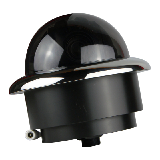
Page 4: Camera Dimensions
Camera Dimensions Rev: 01.01 / 18-06-19... -
Page 5: Conventions
Conventions: At various points within this guide, the following icons are used to illustrate important and/ or potentially dangerous information: INFORMATION: This symbol points out important information pertaining to the installation, operation and maintenance of the camera. WARNING: This symbol indicates a risk of damaging the camera or other items, or an important issue that may effect the operation of the camera. -
Page 6: Limited Warranty
For products purchased through unauthorised dealers or online resellers, any warranty claims should be made against the seller and not Iris. Iris is not liable for any warranty claim made on products purchased through unauthorised vendor. - Page 7 THEN SUCH WARRANTIES ARE LIMITED IN DURATION TO THE DURATION OF THIS LIMITED WARRANTY. IN NO EVENT SHALL IRIS BE LIABLE IN A CLAIM FOR BREACH OF WARRANTY FOR ANY INCIDENTAL, SPECIAL, INDIRECT OR CONSEQUENTIAL DAMAGES, WHETHER RESULTING FROM THE USE, MISUSE OR INABILITY TO USE THIS PRODUCT OR FROM DEFECTS IN THE PRODUCT. ...
-
Page 8: Warnings & Product Information
Warnings & Product Information: LEGAL NOTICE: In some jurisdictions it could be considered an invasion of privacy rights to take or publicly display photographs or videos of people or their vehicles using this product. It is your responsibility to know and comply with applicable laws and rights to privacy I your jurisdiction. - Page 9 Operating the camera or viewing the video input whilst the vessel is moving could cause a distraction and result in accidental collision resulting in property damage, injury or death. Iris Innovations cannot be held liable for any incidental, special, indirect or consequential damages whether resulting from the use, misuse or inability to use this product.
- Page 10 The dome cover has a protective coating which may suffer damage as a result of improper cleaning. To clean the dome use a soft cotton cloth. Moisten with clean water if necessary. For further advise on cleaning the lens window, contact Iris Innovations. INFORMATION: PRODUCT DISPOSAL AND RECYCLING Dispose of this product in accordance with the WEEE Directive.
-
Page 11: Package Contents
Package Contents: Please unpack your new Sentinel camera and check to make sure the following items are included in the box. If there are any items missing please contact your Iris dealer immediately: • The Manual (obviously ;-) • IRIS106 Camera •... -
Page 12: Typical Configuration Examples
Below is an example of a system with 2 controllers and 2 cameras. An IRISEXP0204 data expander has been used to manage the data cables, and an IRIS-HVR4 Recorder / Switcher has been used to manage the two video feeds. -
Page 13: Using Web Encoders To Connect An Analogue Camera To A Network
+12VDC ±10% Compatibility Information: Compatibility with MFDs: IRIS106 cameras all have an analogue video output (even the IP modules) compatible with all MFDs that feature a composite video input. IP camera compatibility depends on the make and model of your MFD. - Page 14 Certain IP Encoders also support RS485 connections specifically to drive PTZ cameras such as the IRIS106 but this feature will only work if it features in your MFD’s software. Iris are working with MFD manufacturers to integrate camera control into chart plotter interfaces.
-
Page 15: Camera Control
Camera Control IRIS106 cameras are controlled via an RS485 serial data connection, using a variant of the Pelco-D CCTV camera control protocol. The Pelco-D protocol was designed to provide accurate controls for a wide range of standard CCTV features, such as pan, tilt, user preset features etc, but do not include certain extended features supported by Iris cameras. -
Page 16: Power Connections
Use 75Ω Coaxial cable such as RG59. Please note, RG59 has a solid core conductor which may not be suitable. In this case use a stranded coaxial cable such as URM70. A BNC ʻstraight-thruʼ adapter is supplied with the IRIS106 in case you need to extend the video cable run. -
Page 17: Serial Data Connections
2 wires usually labelled either A and B or + and -. The data wires from the 106 umbilical cable are identified accordingly: RED: RS485 A (RS485+) / Black: RS485 B (RS485-) When connecting directly to an IRIS595 controller, observe the following polarity: IRIS106 Cable Umbilical Function IRIS595 Controller RS485 A (+) -
Page 18: Connecting Multiple Cameras & Controllers
Controllers are referred to as Inputs and cameras are referred to as outputs. If you require more than 2 controller inputs contact Iris for details of how to configure your system. Page 12 shows an example of how Serial Data Distributors can be used. In this example the system consists of IP cameras being controlled via RS485, and using a Serial Data Distributor to facilitate multiple controllers and cameras. -
Page 19: Camera Addressing
Analogue Camera Addressing: Set the address for your IRIS106 via the bank of DIP switches the can be located by removing the dome cover as shown in the image below:... -
Page 20: Installation
Installation Installation Considerations It's important to fully consider the intended position of the camera and the desired fields of view prior to installation, in terms of how you are going to get cables to the position, will the camera be able to see the appropriate areas, will the camera interfere with any other fixture such as a doorway or walkway once it's fixed in place, or are there any obstructions behind the surface onto which the camera is to be installed. - Page 21 Step 1: After you have established the desired mounting position and are happy there are no obstacles behind the surface into which you are drilling, use a 105mm hole saw to carefully create the circular recess into which the camera body will sit. Step 2: Once the mounting hole has been cut offer the camera into place and mark off...
-
Page 22: Operation
Operation Powering Up / Initialisation: Never apply power to the camera unless all connections are terminated correctly. Never disconnect the DC ground for any reason whilst the camera is powered up as this could result in damage to the electronic circuitry. Upon switching on the circuit breaker that isolates the camera, the unit will perform an initialisation routine. - Page 23 • Use UP and Down to change values • To save changes use Iris OPEN. To un-save use Iris CLOSE Important: Changing certain values within the OSD menu can effect the control of the camera and it’s functionality. It is greatly recommended that values within the OSD are left as default.
- Page 24 Rev: 01.01 / 18-06-19...
Need help?
Do you have a question about the IRIS106 and is the answer not in the manual?
Questions and answers