Advertisement
Advertisement

Related Manuals for Takeuchi TB23R


Summary of Contents for Takeuchi TB23R
- Page 2 FOREWORD This manual is intended for persons who engage in maintenance operations, and explains procedures for dis- assembly and reassembly of the machine, check and maintenance procedures, maintenance reference values, troubleshooting and outline specifications, etc. Please use this manual as a reference in service activities to improve maintenance techniques.
- Page 3 I . GENERAL II . SPECIFICATIONS III . MACHINE CONFIGURATION IV . HYDRAULIC UNITS V . TROUBLESHOOTING VI . ENGINE...
- Page 4 I . GENERAL...
-
Page 5: Table Of Contents
GENERAL CONTENTS Safety precautions ..............................3 Cautions during Disassembly and Assembly ......................9 Cautions during Removal and Installation of the Hydraulic Units .................9 Cautions during Removal and Installation of Piping ....................10 Handling of Seals ..............................10 Tightening Torques ............................... 11... -
Page 6: Safety Precautions
GENERAL SAFETY PRECAUTIONS SAFETY ALERT SYMBOL This symbol means Attention! Be Alert! Your Safety Is Involved. The message that follows the symbol contains important information about safety. Read and understand the message to avoid personal injury or death. ■ SIGNAL WORDS Safety messages appearing in this manual and on machine decals are identified by the words “DANGER”, “WARNING”... - Page 7 GENERAL Provide a fire extinguisher and first aid Anti-explosive lighting Use anti-explosive electrical fixtures and lights • Know where a fire extinguisher and first aid kit when inspecting fuel, oil, coolant, battery fluid, etc. are located and understand how to use them. If lighting that is not anti-explosive should break, •...
- Page 8 GENERAL Always clean the machine Securely block the machine or any com- ponent that may fall • Clean the machine before performing mainte- nance. • Before performing maintenance or repairs under • Cover electrical parts when washing the machine. the machine, set all working equipment against Water on electrical parts could cause short-cir- the ground or in the lowermost position.
- Page 9 GENERAL Cautions on working on the machine Handling of hoses Fuel, oil or hydraulic fluid leaks can cause a fire. • Do not twist, bend or hit the hoses. • Never use twisted, bent or cracked hoses, tubes and pipes. They may burst. •...
- Page 10 • Do not make hole, weld, or fuse. • Do not subject to shock such as hitting or rolling. • At time of disposal, it will be necessary to release the enclosed gas. Please contact a Takeuchi sales or service agent. Be careful with grease under pressure Pressure can be maintained in the hydraulic circuit long after the engine has been shut down.
- Page 11 Have a Takeuchi service agent repair welding cracks or other damage Ask a Takeuchi service agent to repair any welding problems which are detected. If not feasible, make sure the welding is done by a qualified person in a properly equipped workplace.
-
Page 12: Cautions During Disassembly And Assembly
GENERAL CAUTIONS DURING DISASSEMBLY AND CAUTIONS DURING REMOVAL AND INSTALLA- ASSEMBLY TION OF THE HYDRAULIC UNITS 1. Clean the machine before disassembly opera- 1. Make sure that the hydraulic oilʼs temperature tion. has dropped. 2. Before disassembly, check the machine condi- 2. -
Page 13: Cautions During Removal And Installation Of Piping
GENERAL CAUTIONS DURING REMOVAL AND INSTAL- HANDLING OF SEALS LATION OF PIPING 1. Clean the grooves for O-rings and if there is any 1. When hydraulic hoses are installed, tighten them burr, etc., remove it. once to the prescribed torque, then loosen them slightly and retighten them to the prescribed torque. -
Page 14: Tightening Torques
GENERAL TIGHTENING TORQUES Hydraulic Hoses Torque UNION NUT Hose Fitting Size Union Nut (G) Taper Thread (R) N·m ft-lb N·m ft-lb +4.9 +3.5 11.8 ±1.2 8.7 ±0.8 TAPER THREAD +4.9 +3.5 24.5 18.1 29.4 ±2.9 21.7 ±2.1 +4.9 36.2 +3.5 53.9 ±5.4 39.8 ±3.9 58.8... - Page 15 GENERAL Joints for Piping Torque Nominal Thread Diameter Steel Cast Steel N·m ft-lb N·m ft-lb 11.8 ±1.2 8.7 ±0.8 10.8 ±1.1 8.0 ±0.7 29.4 ±2.9 21.7 ±2.1 24.5 ±2.5 18.1 ±1.7 53.9 ±5.4 39.8 ±3.9 49 ±4.9 36.2 ±3.5 88.3 ±8.8 65.1 ±6.4 73.5 ±7.4 54.3 ±5.3...
- Page 16 GENERAL Bolts and Nuts (for ISO Strength Category 10.9) Torque Thread Size × Pitch General Tightening Points Special Tightening Points N·m kgf·m ft-lb N·m kgf·m ft-lb × 9.8 ±0.5 1.0 ±0.05 7.2 ±0.4 11.8 ±0.6 1.2 ±0.06 8.7 ±0.4 × 1.25 22.6 ±1.1 2.3 ±0.11 16.6 ±0.8...
- Page 17 II . SPECIFICATIONS II-1...
- Page 18 SPECIFICATIONS CONTENTS Names of Components ............................3 Dimensions ................................4 Machine Dimensions ............................4 Operating Ranges .............................5 Lifting Capacities ..............................6 Specifications Tables ...............................9 Specifications ..............................9 Specifications of Devices ..........................10 Mass Tables ................................12 Unit Mass (Dry Mass) ............................12 Recommended Lubricants ............................13 Servicing Standards ..............................14 Travel System ..............................14 Working Equipment ............................15 Standards for Judging Performance ........................16...
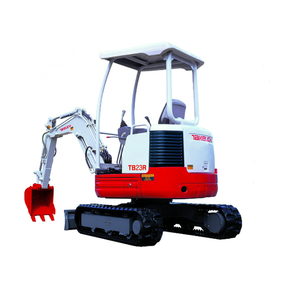
- Page 19 SPECIFICATIONS NAMES OF COMPONENTS NAMES OF COMPONENTS 1. Canopy 12. Idler 23. Boom 2. Engine Hood 13. Track Roller 24. Boom Cylinder 3. Fuel Tank 14. Shoe Slide 25. Swing Bracket 4. Hydraulic Tank 15. Travel Motor 26. Swing Cylinder 5.
- Page 20 BUY NOW Then Instant Download the Complete Manual Thank you very much! ...
Need help?
Do you have a question about the TB23R and is the answer not in the manual?
Questions and answers