Table of Contents

Related Manuals for Phcbi MDF-MU500H


Summary of Contents for Phcbi MDF-MU500H
- Page 1 Operating Instructions Biomedical Freezer MDF-MU500H MDF-MU300H MDF-MU500H Please read the operating instructions carefully before using this product, and keep the operating instructions for future use. See page 32 for all model numbers.
-
Page 3: Table Of Contents
CONTENTS INTRODUCTION P. 2 PRECAUTIONS FOR SAFE OPERATION P. 3 ENVIRONMENTAL CONDITIONS P. 7 FREEZER COMPONENTS P. 8 Control panel P. 10 INSTALLATION SITE P. 11 INSTALLATION P. 12 START-UP OF UNIT P. 13 CHAMBER TEMPERATURE SETTING P. 14 KEY LOCK FUNCTION P. -
Page 4: Introduction
INTRODUCTION ■ Read the operating instructions carefully before using the product and follow the instructions for safe operation. ■ PHC Corporation takes no responsibility for safety if the product is not used as intended or is used with any procedures other than those given in the operating instructions. ■... -
Page 5: Precautions For Safe Operation
PRECAUTIONS FOR SAFE OPERATION It is imperative that the user complies with the operating instructions as it contains important safety advice. Items and procedures are described so that you can use this unit correctly and safely. If the precautions advised are followed, this will prevent possible injury to the user and any other person. - Page 6 PRECAUTIONS FOR SAFE OPERATION WARNING Do not use the unit outdoors. Current leakage or electric shock may result if the unit is exposed to rain water. Only qualified engineers or service personnel should install the unit. The installation by unqualified personnel may cause electric shock or fire. Install the unit on a sturdy floor and take an adequate precaution to prevent the unit from turning over.
- Page 7 PRECAUTIONS FOR SAFE OPERATION WARNING Ensure you do not inhale or consume medication or aerosols from around the unit at the time of maintenance. These may be harmful to your health. Never splash water directly onto the unit as this may cause electric shock or short circuit. Never put containers with liquid on the unit as this may cause electric shock or short circuit when the liquid is spilled.
- Page 8 PRECAUTIONS FOR SAFE OPERATION CAUTION This unit must be plugged into a dedicated circuit protected by branch circuit breaker. Use a dedicated power source as indicated on the rating label attached to the unit. A multiple-tap may cause fire resulting from abnormal heating. Connect the power supply plug to the power source firmly after removing the dust on the plug.
-
Page 9: Environmental Conditions
ENVIRONMENTAL CONDITIONS This equipment is designed to be safe at least under the following conditions (based on the IEC 61010-1): ■ Indoor use; ■ Altitude up to 2000 m; ■ Ambient temperature 5 C to 40 ■ Maximum relative humidity 80% for temperature up to 31 C decreasing linearly to 50% relative humidity at 40 ■... -
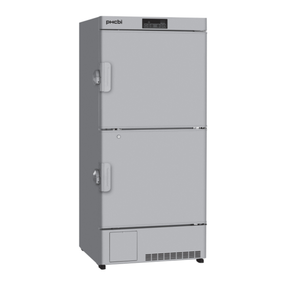
Page 10: Freezer Components
FREEZER COMPONENTS Fixture Hole for padlock Power switch Power cord Back MDF-MU300H Fixture Spacer Power switch Power cord Back MDF-MU500H... - Page 11 FREEZER COMPONENTS 1. Keyhole: By turning to 180 degree to counterclockwise with a key, the door can be locked. 2. Handle: To open the door, grip the handle. 3. Door: Always grip the handle to open the door. 4. Leveling foot: Serves to adjust the height and to settle the frame evenly. 5.
-
Page 12: Control Panel
FREEZER COMPONENTS Control panel 1. Alarm lamp (ALARM): This lamp is flashed when unit is in alarm status. See page 18. 2. Digital temperature indicator: Normally, the current chamber temperature or set temperature is displayed. In alarm status, an error code and chamber temperature is displayed alternately. See page 3. -
Page 13: Installation Site
Leave at least 10 cm around the unit for ventilation. Poor ventilation will result in a reduction of the performance and consequently the failure. For MDF-MU500H, avoid the direct air flow by the air conditioner to the back side because the wire condenser is on the back. -
Page 14: Installation
Ensure the unit is level. Leveling foot 3. Keeping the space (MDF-MU500H only) Keep the adequate space at the back of the unit by using the spacer on the back. To fix the spacer, follow the procedure below. -
Page 15: Start-Up Of Unit
START-UP OF UNIT Follow the procedures for the initial and consequent operations of the unit. 1. Connect the power cord to the dedicated outlet with appropriate rating with the chamber empty and turn on the power switch. 2. Turn on the battery switch when the battery mounting box (optional component) is installed. 3. -
Page 16: Chamber Temperature Setting
CHAMBER TEMPERATURE SETTING Table 1 shows the basic procedure for setting the chamber temperature. Perform key operations in the sequence indicated in the table. The example in the table is based on the assumption that the desired temperature is -25 Note: The unit is set at the factory that the set temperature is -30 Table 1 Basic operation sequence (Example: Chamber temperature -25 Description of operation... -
Page 17: Alarm Temperature Setting
ALARM TEMPERATURE SETTING This unit is provided with both high and low temperature alarms. The temperature at which the alarm is activated can be changed. Note: The temperature alarm is set at ±10 C of the chamber set temperature at the factory. Display Mode Available set range... -
Page 18: Setting Of Alarm Resume Time
SETTING OF ALARM RESUME TIME The alarm buzzer and remote alarm are stopped by pressing alarm buzzer stop key (BUZZER) on the control panel during alarm condition. The buzzer and remote alarm will be activated again after certain suspension if the alarm condition is continued. The suspension time can be set by following the procedure shown in the Table 5 below. -
Page 19: Setting Of Compressor Delay Time
SETTING OF COMPRESSOR DELAY TIME The delay time of low stage side compressor can be set to reduce the load on the power line and to facilitate the start-up (reset) of the freezer after power failure. The example in the table is based on the assumption that the delay time is changed to 4 minutes. The delay time is set to 1 minutes at the factory. -
Page 20: Alarms & Safety Functions
ALARMS & SAFETY FUNCTIONS This unit has the alarms and safety functions shown in Table 7, and also self diagnostic functions. Table 7 Alarms and safety functions Alarm & Safety Situation Indication Buzzer Safety operation If the chamber temperature is higher Alarm lamp is flashed. -
Page 21: Routine Maintenance
2. Remove all storage containers other than the empty defrost water vessel & storage container (MDF-MU300H) or the bottom storage container (MDF-MU500H). 3. Press the defrost key (DEF) for 5 seconds to stop the refrigerating operation. While the refrigerating operation is stopped, the current chamber temperature and dF is displayed on the control panel alternately. -
Page 22: Troubleshooting
TROUBLE SHOOTING If the unit malfunctions, check out the following before calling for service. Malfunction Check/Remedy The chamber is not cooled ■ The power cord is not connected to the outlet. at all ■ The circuit breaker of power source is active. ■... -
Page 23: Disposal Of Unit
DISPOSAL OF UNIT WARNING Flammable and explosive product. This product contains flammable refrigerant. Be sure to follow the below instructions when servicing or recycling. • Well ventilate the room to prevent refrigerant accumulation. • Keep fire away when the refrigerant is contained in the product. •... - Page 24 DISPOSAL OF UNIT (English) Information on Disposal for Users of Waste Electrical & Electronic Equipment (private households) This symbol on the products and/or accompanying documents means that used electrical and electronic products should not be mixed with general household waste. For proper treatment, recovery and recycling, please take these products to designated collection points, where they will be accepted on a free of charge basis.
- Page 25 DISPOSAL OF UNIT (French) Informations relatives à l’évacuation des déchets, destinées aux utilisateurs d’appareils électriques et électroniques (appareils ménagers domestiques) Lorsque ce symbole figure sur les produits et/ou les documents qui les accompagnent, cela signifie que les appareils électriques et électroniques ne doivent pas être jetés avec les ordures ménagères.
- Page 26 DISPOSAL OF UNIT (Portuguese) Informações sobre a eliminação de resíduos para utilizadores de equipamentos eléctricos e electrónicos (utilizadores particulares) Este símbolo nos produtos e/ou documentos anexos significa que os produtos eléctricos e electrónicos usados não devem ser misturados com os resíduos urbanos indiferenciados. Para efectuar um tratamento, recuperação e reciclagem correctos, leve estes produtos para pontos de recolha próprios para o efeito, onde serão aceites gratuitamente.
- Page 27 DISPOSAL OF UNIT (Dutch) Informatie over weggooien elektrische elektronische apparatuur (particulieren) Dit symbool betekent in Europa dat gebruikte elektrische en elektronische producten niet bij het normale huishoudelijke afval mogen. Lever deze producten in bij de aangewezen inzamelingspunten, waar ze gratis worden geaccepteerd en op de juiste manier worden verwerkt, teruggewonnen en hergebruikt.
-
Page 28: Temperature Recorder (Option)
MTR-4015LH or MTR-G85C. For the attachment, the recorder fixing is necessary. Following shows the combination of recorder and the recorder fixing: Freezer Attachment location Temperature recorder Recorder fixing MDF-MU500H Lower front MTR-4015LH MPR-S30 MTR-G85C MPR-S7 MDF-MU300H MTR-4015LH... - Page 29 TEMPERATURE RECORDER (OPTION) 5. Slide the recording paper along the guide plate so that the recording paper will not be forced out of the date & Notch for time adjustment slot. See Fig. 5. date & time adjustment 6. After ascertaining that the holes on the side of the recording paper are locked into the teeth of the sprocket, turn the gear and send the recording paper into the used recording paper storage.
-
Page 30: Setting Of Mtr-G85C
TEMPERATURE RECORDER (OPTION) Setting of MTR-G85C If the warning is required for the internal temperature record or the interior temperature deviates from the target temperature, an optional temperature recorder (MTR-G85C) is available. Install the recorder properly as described below. Chart guides Pen cap holder Back-up battery Pen arm... - Page 31 TEMPERATURE RECORDER (OPTION) Starting recording and setting the time: Turn the power switch ON. The ink pen will move inward on the recording paper and stop temporarily at the 0% Ink pen position (equivalent to the 40 C line). Then the ink pen will move to the position which indicates the measured Hour temperature.
-
Page 32: Battery Mounting Box (Option)
BATTERY MOUNTING BOX (OPTION) The alarm indicator blinks and the alarm buzzer sounds to notice the power failure when a battery for power failure alarm is installed. In addition, the remote alarm is available. For the installation of the battery for power failure alarm, a battery mounting box (MPR-48B1), an optional component is necessary. A battery for power failure alarm and remote alarm terminal are included in the battery mounting box. -
Page 33: Specifications
Weight 76 kg 124 kg Temperature recorder (MTR-4015LH or MTR-G85C) Recorder fixing (MPR-S30): for MTR-4015LH in MDF-MU500H Recorder fixing (MDF-S740T): for MTR-G85C in MDF-MU300H Optional component Recorder fixing (MPR-S7): for MTR-G85C in MDF-MU500H Battery mounting box (MPR-48B1) Interface board (MTR-480) •... -
Page 34: Performance
80 W 80 W Noise level 40 dB [A] (background noise; 20 dB) Maximum pressure 1060 kPa Product name Biomedical Freezer MDF-MU500H Model No. MDF-MU500H-PE Cooling performance C (ambient temperature; 30 C, no load) Temperature control range C to -30... -
Page 35: Safety Check Sheet
CAUTION Please fill in this form before servicing. Hand over this form to the service engineer to keep for his and your safety. Safety check sheet 1. Freezer contents : □ □ Risk of infection: □ □ Risk of toxicity: □... - Page 36 1-1-1 Sakada, Oizumi-machi, Ora-gun, Gunma 370-0596, Japan Printed in Japan LDCL034000-0 © PHC Corporation 2018 S0418-0...
Need help?
Do you have a question about the MDF-MU500H and is the answer not in the manual?
Questions and answers