Table of Contents
Advertisement
Quick Links
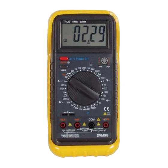
True RMS Digital Multimeter
1 Safety information
This multimeter has been designed according to IEC - 1010 concerning
electronic measuring instruments with an overvoltage category (CAT II) and
pollution 2.
Follow all safety and operating instructions to ensure that the meter is used
safely and is kept in good operating condition.
1.1 Preliminary
•
When using the meter, the user must observe all normal safety rules
concerning :
- Protection against the dangers of electrical current.
- Protection of the meter against misuse.
•
Full compliance with safety standards can be guaranteed only if used with
test leads supplied. If necessary, they must be replaced with the same model
or same electric ratings. Measuring leads must be in good condition.
1.2 During use
•
Never exceed the protection limit values indicated in specifications for each
range of measurement.
•
When the meter is linked to a measurement circuit, do not touch unused
terminals.
•
When the value scale to be measured is unknown beforehand, set the range
selector at the highest position.
•
Before rotating the range selector to change functions, disconnect test leads
from the circuit under test.
•
When carrying out measurements on TV or switching power circuits, always
remember that there may be high amplitude voltage pulses at test points
which can damage the meter.
•
Never perform resistance measurements on live circuits.
DVM98
Advertisement
Table of Contents

Related Manuals for Velleman DVM98


Summary of Contents for Velleman DVM98
- Page 1 DVM98 True RMS Digital Multimeter 1 Safety information This multimeter has been designed according to IEC - 1010 concerning electronic measuring instruments with an overvoltage category (CAT II) and pollution 2. Follow all safety and operating instructions to ensure that the meter is used safely and is kept in good operating condition.
-
Page 2: Maintenance
1.3 Symbols Important safety information, refer to the operating manual. Dangerous voltage may be present. Earth ground Double insulation (Protection class II). 1.4 Maintenance • Before opening the meter, always disconnect test leads from all sources of electric current. • For continue protection against fire, replace fuse only with the specified voltage and current ratings : F : F 200mA/250V... - Page 3 1. POWER SWITCH 2. DATA-HOLD SWITCH 3. CAPACITOR MEASURING SOCKET 4. LCD DISPLAY 5. TRANSISTOR TESTING SOCKET 6. ROTARY SWITCH 7. INPUT JACKS...
- Page 4 2.1 Function and Range Selector There are totally 10 functions and 32 ranges provided. A rotary switch is used to select functions as well as ranges. 2.2 Power Switch A push - push switch is used to turn the meter on or off. To extend the battery life, Auto Power-Off function is provided.
-
Page 5: Measuring Voltage
3. Operating Instruction 3.1 Measuring voltage 1. Connect the black test lead to the COM jack and the red test lead to the V Ω Hz jack. 2. Set the rotary switch at the desired V or V range position and connect test leads across the source or load under measurement. -
Page 6: Measuring Resistance
3.4 Measuring resistance 1. Connect the black test lead to the COM jack and the red test lead to the V Ω Hz jack. ( The polarity of red lead is "+"). 2. Set the rotary switch at desired Ω position and connect test leads across the resistor under measurement. -
Page 7: Testing Transistor
3.7 Testing transistor 1. Set the rotary switch at hFE position. 2. Determine whether the transistor to be tested is NPN or PNP type and locate the Emitter, Base and Collector leads. Insert leads of the transistor into proper holes of the transistor testing socket. 3. - Page 8 4.2 DC voltage Range Resolution Accuracy 200mV 0.01mV + 0.05% of rdg + 3 digits 0.1mV + 0.1% of rdg + 3 digits + 0.1% of rdg + 3 digits 200V 10mV + 0.1% of rdg + 3 digits 1000V 0.1V + 0.15% of rdg + 5 digits Input Impedance : 10MΩ...
- Page 9 4.6 Resistance Range Resolution Accuracy + 0.5% of rdg + 10 digits 200Ω 0.01Ω + 0.3% of rdg + 10 digits 2kΩ 0.1Ω + 0.3% of rdg + 10 digits 20kΩ 1Ω + 0.3% of rdg + 10 digits 200kΩ 10Ω...
-
Page 10: How To Use The Holster
5.1 How to use the holster The holster is used to protect the meter and to make the measurement more comfortable. It comes with two stands installed together. The figure shows how to use the holster to : 1. Support the meter with a standard angle. (fig. a) 2. -
Page 11: Battery And Fuse Replacement
5.2 Battery & Fuse Replacement If the sign " " appears on the LCD display, it indicates that battery should be replaced. Remove screws on the back cover and open the case. Replace the exhausted battery with a new one. Fuse rarely need replacement and blow almost always as a result of the operator’s error.
Need help?
Do you have a question about the DVM98 and is the answer not in the manual?
Questions and answers