
Related Manuals for Gossen MetraWatt PROFITEST H+E BASE


Summary of Contents for Gossen MetraWatt PROFITEST H+E BASE
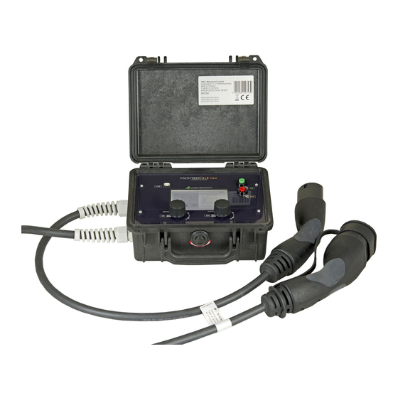
- Page 1 Operating Instructions PROFITEST H+E BASE Diagnostics Unit for Electric Charging Stations 3-349-876-03 (Type 2 Connector Socket) 1/3.16 1.800.544.2843 www.calcert.com sales@calcert.com...
-
Page 2: Table Of Contents
Operating Instructions PROFITEST H+E BASE Table of Contents General Notes ............................1 Explanation of Symbols ........................1 Basic Safety Precautions ........................2 Product Overview..........................3 Initial Start-Up ............................9 Diagnosis of Charging Points with the Diagnostics Unit ..............10 Language Selection ..........................13 Errors .............................. -
Page 3: Basic Safety Precautions
2 connector socket (mode 3 charging). Use for other purposes is prohibited. Target Group Only trained, qualified electricians may use the PROFITEST H+E BASE diagnostics unit. Trained, qualified electricians fulfill the following requirements: Knowledge of general and specific accident prevention regulations ... -
Page 4: Product Overview
Operating Instructions PROFITEST H+E BASE Product Overview Scope of Delivery PROFITEST H+E BASE diagnostics unit Two 9 V block batteries 12 V power pack Operating instructions Device Layout 1 Protective cover 2 Power pack connector socket (12 V, 1 A) - Page 5 Operating Instructions PROFITEST H+E BASE Control Panel Layout 1 Rotary mode selector switch and OK button 2 Rotary status selector switch and escape button 3 Off button 4 On button (the button has to be pressed and held for several seconds in order to switch...
- Page 6 Operating Instructions PROFITEST H+E BASE Display Layout The display is subdivided into various blocks: 1 Vehicle States 2 Cable Condition 3 Error States Page 5 1.800.544.2843 www.calcert.com sales@calcert.com...
- Page 7 Operating Instructions PROFITEST H+E BASE 4 PWM Signal Evaluation 5 Phases and Phase Sequence 6 Battery Level Page 6 1.800.544.2843 www.calcert.com sales@calcert.com...
- Page 8 Operating Instructions PROFITEST H+E BASE Displays The following symbols with the meanings shown below can appear at the display: Vehicle States No vehicle connected Vehicle connected Vehicle not ready Vehicle ready to charge No ventilation required Ventilation required Cable Condition...
- Page 9 Operating Instructions PROFITEST H+E BASE Error States Diode OK Diode short-circuited CP OK CP short-circuited to PE No RCD tripping RCD tripping Phases and Phase Sequence Phase L1 switched on Phase L2 switched on Phase L3 switched on Clockwise phase sequence...
-
Page 10: Initial Start-Up
Operating Instructions PROFITEST H+E BASE Initial Start-Up General Warning! Danger! The device should be checked to assure that it’s in good condition before initial start-up. The device may only be used by trained personnel. Inserting the Batteries The device can be operated with two rechargeable or regular 9 V block batteries. The two battery compartments (3) on the right side of the device are opened in order to insert the batteries. -
Page 11: Diagnosis Of Charging Points With The Diagnostics Unit
Operating Instructions PROFITEST H+E BASE Connecting a Test Consumer The diagnostics unit is equipped with an earthing contact socket (6) to which a test consumer can be connected. Any desired test consumer (230 V, max. 13 A) can be connected in order to test a charging point under load. - Page 12 Operating Instructions PROFITEST H+E BASE 1.5 KΩ 13 A 680 Ω 20 A 220 Ω 32 A 100 Ω 63 A Fault Simulation The diagnostics unit is equipped with an option for simulating common errors (see pages 6 and 9).
- Page 13 Operating Instructions PROFITEST H+E BASE State C, + 6 V, vehicle ready for charging without ventilation State D, + 3 V, vehicle ready for charging with ventilation Negative voltage In the event of correct functioning, voltage is - 12 V. If the diode is short-circuited (by means of simulation), negative voltage is the same as positive voltage (but with the opposite preceding sign).
-
Page 14: Language Selection
Operating Instructions PROFITEST H+E BASE Operating the Diagnostics Unit with the Rotary Switches The two rotary switches (1 and 2) are used to operate the diagnostics unit. The device is switched from one mode to the other by turning the rotary mode selector switch (1). -
Page 15: Errors
Operating Instructions PROFITEST H+E BASE Errors Error Cause Required Action After being switched on, the On button not pressed long Press and hold the on button device switches itself back off enough. until the device remains on. again. The device does not respond... -
Page 16: Appendix: Practical Information On Testing Charging Points
Operating Instructions PROFITEST H+E BASE Appendix: Practical Information on Testing Charging Points Type II Plug for Mode 3 Charging Source: Mennekes Resistance Coding for Charging Cables Table B.101 – Resistor Codings for Plugs Recommended Nominal resistance of Rc Current capacity of the cable assembly interpretation range Tolerance 3%... - Page 17 Operating Instructions PROFITEST H+E BASE Typical Pilot Electric Equivalent Circuit for Mode 3 Charging Typical pilot electric equivalent circuit Source: IEC 61851 Page 16 1.800.544.2843 www.calcert.com sales@calcert.com...
- Page 18 Operating Instructions PROFITEST H+E BASE Typical Pilot Electric Equivalent Circuit for Mode 3 Charging Table A.2 – Vehicle Control Pilot Circuit Values and Parameters (see figures A.1 and A.2) Parameter Symbol Value Value Range Units Permanent resistor value 2,740...
- Page 19 Operating Instructions PROFITEST H+E BASE System States PWM Voltage – Table A.3 – System States EVSE ready System connected ready to supply Remark High state to the receive supply energy level level EVSE energy energy 12 V Steady = 0 V...
- Page 20 Operating Instructions PROFITEST H+E BASE System States PWM Voltage – Table A.201 – Pilot Voltage Range The following table details the pilot voltage range as a result of tables A.1 and A.2 components values. These voltage ranges applies to the EVSE (Va).
- Page 21 Operating Instructions PROFITEST H+E BASE System States Duty Cycle – Table A.6 – Maximum Current to be Drawn by the Vehicle Nominal duty cycle Maximum current to be drawn by vehicle interpretation by vehicle Duty cycle < 3% Charging not allowed 3% ...
- Page 22 Operating Instructions PROFITEST H+E BASE System States Duty Cycle – Page 21 1.800.544.2843 www.calcert.com sales@calcert.com...
- Page 23 Operating Instructions PROFITEST H+E BASE Diagnostics Unit for Testing Charging Points Vehicle simulation A charging point is more than just a simple electrical outlet and it only functions when a vehicle is detected. The diagnostics unit is capable of simulating a vehicle.
- Page 24 Operating Instructions PROFITEST H+E BASE Diagnosis Procedure for a Charging Point Switch back and forth between states. Check parameters and turn-off times. Switch back and forth between cables. Check parameters. Trigger errors. Check system performance.
- Page 25 Operating Instructions PROFITEST H+E BASE Error diagnosis: Error: L2 not connected or fuse L2 blown Error diagnosis: Error: No PWM signal Signal generation or cable connection defective Page 24 1.800.544.2843 www.calcert.com sales@calcert.com...
- Page 26 Operating Instructions PROFITEST H+E BASE Error diagnosis: Error: Incorrect values for duty cycle and charging current Cable detection defective Error diagnosis: Error: Erroneous values for PWM, voltage and frequency Signal generation defective CP and PP connections reversed Page 25 1.800.544.2843 www.calcert.com...
Need help?
Do you have a question about the PROFITEST H+E BASE and is the answer not in the manual?
Questions and answers