Table of Contents
Advertisement
Quick Links
For Indoor Applications Only:
Commercial Applications:
CHS19980HEiP . .......... 80 Gallon, 199,000 BTU
CHS1998HEiN . ............ 80 Gallon, 199,000 BTU
CHS19980HEXiN . ........ 80 Gallon, 192,000 BTU
Residential Applications:
RHS19980HEiP . .......... 80 Gallon, 199,000 BTU
RHS1998HEiN . ............ 80 Gallon, 199,000 BTU
RHS19980HEXiN . ........ 80 Gallon, 192,000 BTU
The Commercial Hybrid System is assembled with multiple and separately certified
components consisting of:
•
RL94i / RLX94i Tankless Water Heater
•
80 Gallon Storage Tank
•
Controller
READ ALL OF THE INSTRUCTIONS THOROUGHLY BEFORE INSTALLING OR
OPERATING THIS SYSTEM.
(This manual is a supplement to the RL94i Installation and Operation
Manual)
This manual provides information on the installation, operation, and maintenance of
the water heater. For proper operation and safety, it is important to follow the
instructions and adhere to the safety precautions.
A licensed professional must install the water heater according to the exact
instructions in this manual.
The consumer must read the entire manual to properly operate the water heater and
to have regular maintenance performed.
WARNING
IF THE INFORMATION IN THESE INSTRUCTIONS IS NOT FOLLOWED EXACTLY, A FIRE OR EXPLOSION MAY
RESULT CAUSING PROPERTY DAMAGE, PERSONAL INJURY OR DEATH.
— Do not store or use gasoline or other flammable vapors and liquids in the vicinity of this or any other
appliance.
— WHAT TO DO IF YOU SMELL GAS
• Do not try to light any appliance.
• Do not touch any electrical switch; do not use any phone in your building.
• Immediately call your gas supplier from a neighbor's phone. Follow the gas supplier's instructions.
• If you cannot reach your gas supplier, call the fire department.
— Installation and service must be performed by a qualified installer, service agency or the gas supplier.
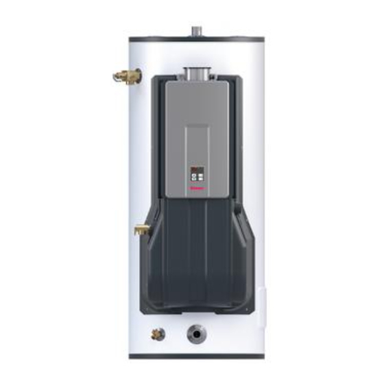
Demand Duo™ 80
Installation and Operation Manual
Advertisement
Table of Contents

Related Manuals for Rinnai CHS1998HEiN


Summary of Contents for Rinnai CHS1998HEiN
- Page 1 Installation and Operation Manual For Indoor Applications Only: Commercial Applications: CHS19980HEiP ... 80 Gallon, 199,000 BTU CHS1998HEiN ..... 80 Gallon, 199,000 BTU CHS19980HEXiN ..80 Gallon, 192,000 BTU Residential Applications: RHS19980HEiP ... 80 Gallon, 199,000 BTU RHS1998HEiN .
-
Page 2: Table Of Contents
TABLE OF CONTENTS Safety Behaviors and Practices for the Piping Diagram for Basic Installations……………….… 13 Consumer and Installer………………………………….……...3 Piping Diagram for Multi-Unit Installations……….….14 Installation Instructions………………………………………...4 Direct Vent Terminal Clearances………………….……..16 Installer Qualifications…………………………………..4 Venting Guidelines………………………………………..….17 Type of Installation………………………………………..4 Condensate………………………………………………..…..19 Installation Steps………………………………………..……4 Final Checklist……………………………………….…...……..20 General Instructions………………………………..……….4 Technical Data…………………………………………...…………...…21 Prepare for Installation………..………….………..…….5... -
Page 3: Safety Behaviors And Practices For The Consumer And Installer
Safety Behaviors and Practices for the Consumer and Installer WARNING • • Before operating, smell all around the appliance Use only your hand to push in or turn the gas area for gas. Be sure to smell next to the floor control knob. -
Page 4: Installation Instructions
The installation must conform with local codes or, • in the absence of local codes, with the National Training in installation of Rinnai water heaters. Fuel Gas Code, ANSI Z223.1/NFPA 54, or the (Training can be accessed on-line at Natural Gas and Propane Installation Code, CSA www.trainingevents.rinnai.us) -
Page 5: Prepare For Installation
General Instructions (Continued) Prepare for Installation INFORMATION Parts included: • If a water heater is installed in a closed water • Commercial Hybrid System supply system, such as one having a backflow preventer in the cold water supply line, means •... -
Page 6: Determine Installation Location
Determine Installation Location • You must ensure that clearances will be met and that Choose the right hand truck to support the weight the vent length will be within required limits. Consider and size of the water heater. Refer to the the installation environment, water quality, and need “Specifications”... - Page 7 REFER TO THE RL94 MANUAL FOR SPECIFIC DETAILS ON: • Approved Vent Manufacturers and Terminations • Termination Clearances • Maximum Vent Length • Flue Installation with Concentric Venting • Consumer Operation Guidelines for the Safe Operation of your Water Heater •...
-
Page 8: Installation Of Gas Supply
Installation of Gas Supply REFER TO THE RL94 MANUAL FOR SPECIFIC DETAILS ON SIZING THE WARNING GAS PIPE. 1. If you are not knowledgeable or qualified to install gas lines or connections, then contact a MUST DO licensed professional to install the gas supply. •... -
Page 9: Connect Electricity
Connect Electricity REFER TO THE RL94 MANUAL FOR : • High Altitude Adjustment WARNING • Vent Length Adjustment Do not use an extension cord or an adapter plug with • Temperature Controller Installation this appliance. The water heating system must be electrically grounded in accordance with local codes and ordinances or, in the absence of local codes, in accordance with the National Electrical Code, ANSI/... -
Page 10: System Controller
CONTROLLER DIAGNOSTICS SYSTEM CONTROLLER The system controller maintains communication between the tank and tankless to effectively control the tank temperature based on the selected temperature on the tankless unit. By reading the tank temperature (J22) and tankless outlet temperature (J2), the System Controller will energize (120V) the pump when the tank temperature drops. -
Page 11: Installation Of Plumbing
Installation of Plumbing Pressure Relief Valve Requirements Temperature-Pressure Relief Valve An approved pressure relief valve (preinstalled) is Requirements required by the American National Standard (ANSI Z21.10.3) for all water heating systems and shall be Install the Temperature-Pressure Relief (T&P) Valve accessible for servicing. -
Page 12: Typical Installations
Typical Installations Hot Water Outlet Hot Water Outlet Valve Temperature-Pressure Relief Valve Hot Water Supply Cold and Hot Unions Cold Water Supply Valve Cold Water Supply Cold Water Supply Thermal Expansion Tank Vent pipe (concentric shown for illus- tration purposes, see venting section for other options) Operation Unit / Temperature Control Drain Pan... -
Page 13: Piping Diagram For Basic Installations
Piping Diagram for Basic Installations Commercial Hybrid Single Unit Circulation Hot Water Supply Line Note: Installation must conform to applicable code and all requirements listed in the installation manual. Balancing valves, equivalent piping, pressure gauges, and temperature gauges are to be used as necessary to ensure proper flow between units. -
Page 14: Piping Diagram For Multi-Unit Installations
Demand Duo™ 80... - Page 15 Check for proper water pressure to the water that the water heater can be easily discon- heater. Minimum water pressure is 50 psi. Rinnai nected, if servicing is required. recommends 60-80 psi for maximum 2.
-
Page 16: Direct Vent Terminal Clearances
Direct Vent Terminal Clearances A vent termination must be installed to bring in combustion air and expel exhaust to the outside. AIR SUPPLY INLET TERMINATION VENT TERMINAL AREA WHERE TERMINAL IS NOT PERMITTTED Clearance in Ref. A also applies to anticipated snow line SNOW... -
Page 17: Venting Guidelines
Do not use PVC/CPVC, ABS, or galvanized material to vent this appliance. If it becomes necessary to access an enclosed vent system for service or repairs, Rinnai is not • Do not cover non-metallic vent pipe and fittings responsible for any costs or difficulties in accessing with thermal insulation. -
Page 18: Condensate
Flue Installation Install the venting termination according to the diagrams and instructions below. Horizontal Termination without using the Condensate Collector WARNING If the condensate collector is not used, the drain * The condensate collector must be used in pipe must be capped to prevent exhaust gases horizontal terminations if a vertical rise in and condensate from entering the building. -
Page 19: Condensate
Condensate • The end of the condensate drain pipe should be Condensate can form in the vent of high efficiency open to the atmosphere. The end should not be direct vent appliances. Without proper drainage, under water or other substances. condensate will damage the heat exchanger. -
Page 20: Final Checklist
Final Checklist □ □ The water heater is not subject to corrosive Confirm that the water heater is rated for the gas compounds in the air. type supplied. □ □ The water supply does not contain chemicals or Confirm that the electricity is supplied from a 120 exceed total hardness that will damage the heat VAC, 60 Hz power source, is in a properly exchanger. -
Page 21: Technical Data
Technical Data - Commercial Product Number CHS19980HEiP CHS19980HEiN CHS19980HEXiN Product Description Hybrid System: Non-condensing tankless, Insulated Storage Tank, Pump & Control Minimum Gas Consumption Btu/h (kW/h) 10,300 (3.0) Maximum Gas Consumption Btu/h (kW/h) 199,000 (58.3) 192,000 (56.3) 80 Gallons Tank Volume (303 Liters) 259 Gallons 251 Gallons... - Page 22 Technical Data - Residential Product Number RHS19980HEiP RHS19980HEiN RHS19980HEXiN Product Description Hybrid System: Non-condensing tankless, Insulated Storage Tank, Pump & Control Minimum Gas Consumption Btu/h (kW/h) 10,300 (3.0) Maximum Gas Consumption Btu/h (kW/h) 199,000 (58.3) 192,000 (56.3) 80 Gallons Tank Volume (303 Liters) 259 Gallons 251 Gallons...
-
Page 23: Dimensions
Dimensions Inches 27.74 Ø24.25 12.13 (HOT) 28.64 30.00 1-1/2” MNPT (HOT) 56.83 62.69 54.28 T&P 64.71 29.29 24.53 4.19 28.66 1-1/2” MNPT COLD (COLD) 3.54 34.05 DRAIN Demand Duo™ 80... -
Page 24: Storage Tank Maintenance
Storage Tank Maintenance Anodes Draining the Storage Tank The storage tank is equipped with two magnesium To completely drain the storage tank: anodes designed to extend the life of the storage 1. Turn the power “OFF” to the system by unplug- tank. -
Page 25: Replacement Parts
Demand Duo™ 80... -
Page 26: Service/Maintenance Log
Service / Maintenance Log Date Service / Maintenance Completed Demand Duo™ 80... - Page 27 Service / Maintenance Log Date Service / Maintenance Completed Demand Duo™ 80...
-
Page 28: Warranty
A timer added to a standard recirculating pump is not considered as on-demand. [2] The Rinnai Limited Warranty for a heat exchanger used in a recirculation system which is controlled through an aquastat / thermostat, or timer, or an on-demand system is 5 years for commercial applications. - Page 29 Limitation on warranties No one is authorized to make any other warranties on behalf of Rinnai America Corporation. Except as expressly provided herein, there are no other warranties, expressed or implied, including, but not limited to warranties of merchantability or fitness for a particular purpose, which extend beyond the description of the warranty herein.
- Page 30 NOTES Demand Duo™ 80...
- Page 31 NOTES Demand Duo™ 80...
- Page 32 100000470(01) 11/2017...
Need help?
Do you have a question about the CHS1998HEiN and is the answer not in the manual?
Questions and answers