
Related Manuals for Aircatglobal VirtualFly SOLO-A


Summary of Contents for Aircatglobal VirtualFly SOLO-A
- Page 1 SOLO A USER'S MANUAL Rev. 1.2 January 2020 FOR Cessna C172SP Skyhawk and Cessna Skylane II RG R182...
-
Page 3: Table Of Contents
TABLE OF CONTENTS 1. IDENTIFICATION OF ELEMENTS 8. TROUBLESHOOTING 8.1. ANOMALY: THE INDICATOR PANEL DISPLAYS “MFS 2. INSTALLATION Status: Searching...” 2.1. CABLE CONNECTION 8.2. ANOMALY: CONNECTION GOES DOWN, IS 2.2. INSTALATION OF FILES IN THE COMPUTER 6 OF INTERMITTENT OR INDICATORS MOVES SHARPLY MFS/P3D 2.3. -
Page 4: Identification Of Elements
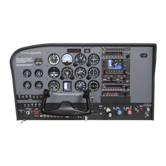
1. IDENTIFICATION OF ELEMENTS Packaging contents: 1. SOLO-A panel (1 unit). 2. SOLO-A Electrical power cable (1 unit). 3. SOLO-A Network cable (1 unit). 4. YOKO+ “the yoke” USB cable (1 unit) (male, male A-B). 5. V3RNIO+ “throttle, propeller, mixture” USB cable (1 unit) (male, male A-A). -
Page 5: Installation
2. INSTALLATION Cable 2 OPTION 1: Direct Switch OFF The SOLO-A, has been technologically developed to be fully plug&play. It connects easily to any computer running the “Microsoft Cable 4 Flight Simulator” or “Prepar3D” hereinafter referred to as “MFS/P3D”. Still, we’ll give you a series of steps to follow to install your panel. The user must consider that SOLO-A has 4 important modules:: • The panel itself: switches, gauges and radiostack • YOKO+ “The yoke”. -
Page 6: Yoko+ & V3Rnio+ Flight Controls
2.2. INSTALLATION OF FILES TO THE COMPUTER OF MFS/P3D Configuration Using VF-Test&Calibrate 1. Open Prepar3D, go to Controls menu, select YOKO+ from the de- FSUIPC Installation vices list. Delete all axis and buttons assignments. Close and open In case you already have FSUIPC installed in your MFS/Prepar3D you Prepar3D again to make sure that settings have been saved. - Page 7 Configuration Using VF-Test&Calibrate 1. O pen FSX-Prepar3D, go to Controls menu, axis assignments section and select TPM V3RNIO from the devices list. Delete all axis assign- ments. Close and open FSX-Prepar3D again to make sure that set- tings have been saved. 2. O pen VFTest&Calibrate-S software, go to TPM V3RNIO tab and se- lect the device from the devices list at right side. 3. V FTest&Calibrate-S has to be running when using TPM V3RNIO be- cause this software reads the data from the device and send it to FSX-Prepar3D so each time you start FSX-Prepar3D, you have to run VFTest&Calibrate-S as well. You can use Windows Scheduler to start VFTest&Calibrate-S automatically.
-
Page 8: Start-Up The Solo-A
3. START UP FIGURE 1 Switch ON Push THE SOLO-A The SOLO-A incorporates a mini-computer that is to be connected to the MFS/P3D computer using the previously mentioned Network cable. It is important to note that in no case should you access or manage the SOLO-A mini-computer. - Page 9 Connected • Once the connection is established, you should see an image like the second. In this case the communication module is searching the MFS/P3d In this case, the MFS/P3Dand SOLO-A are connected and the SOLO-A In this case, the MFS/P3Dand SOLO-A are not connected •...
-
Page 10: Selection Of Panel Type
4. SELECTION OF PANEL TYPE (ACCORDING THE FSX/P3D PLANE ) The SOLO-A can represent 2 panel types of general aviation aircraft, Cessna C172SP Skyhawk and Cessna Skylane II RG R182. Most of the instruments are the same for all both aircraft, whereas other instruments change according to the plane that will be flown. -
Page 11: Radiostack Panel
5. HDG: Heading mode. This follows the Directional Gyro's or HSI's 5. RADIOSTACK PANEL "heading bug". 6. NAV: Navigation mode (VOR 1 or GPS). Arms the NAV mode to inter- cept and follow the selected radial on NAV1/GPS track. 7. APR: Approach mode (LOC or ILS). This arms the APR mode, to inter- Peixsoft GA Radio Stack Displays UDP for Virtual-Fly cept the Localizer and the Glide Slope (if available and the NAV radio is tuned to the ILS frequency). -
Page 12: Communications And Navigation
Display 5.2. COMMUNICATIONS AND NAVIGATION 1. Roll Active Mode: These can be ROL, HDG, NAV, APR and REV. COM & NAV equipment is integrated in the one device. • ROL = Wing Leveler active. • HDG= Heading mode active. COMMUNICATIONS NAVIGATION •... -
Page 13: Automatic Direction Finder (Adf)
5.4. AUTOMATIC DIRECTION FINDER (ADF) Chrono Mode - Elapsed Time (ET) The ET mode allows a chrono with Minutes and Seconds (until 59:59). This is 100% functional; the ADF and BFO buttons are working but per- The chrono begins to count when you press SET/RST push button (also form no actions. -
Page 14: Transponder (Xpdr)
5.5. TRANSPONDER (XPDR) Sequential code full functional XPDR including the flight level in ALT mode. Flight Level, available in Actual Mode XPDR Mode Ident ALT mode indications Code Selector Direct insertion keys (0..7) Clear the last Automatic number inserted VFR code Mode selector This can be changed with the rotatory knob (OFF, SBY, TST, ON, ALT). -
Page 15: Gps Gns-530
6. GPS GNS-530 • Updateable, built-in terrain and navigation databases that contain location reference for all airports, VORs, NDBs, Intersections, Flight Service Stations, published approaches, SIDs/STARs, Special Use Airspace and geopolitical boundaries. • A detailed basemap that shows airports, cities, highways, railroads, rivers, lakes, coastlines and more. - Page 16 6. GPS GNS-530 - SOLO-A USER'S MANUAL...
- Page 17 6. GPS GNS-530 - SOLO-A USER'S MANUAL...
-
Page 18: Multiple Soloflightpanel Or Multiple
7. MULTIPLE SOLO- FLIGHTPANEL OR MULTIPLE MFS/P3D COMPUTER IN THE SAME NETWORK If you connect more than one SOLO-A to the same network, you should be aware that to use them simultaneously you should have more than one computers using MFS/P3D connected to the same network and in- dicate the right MFS/P3D computer to each SOLO-A, as detailed below. -
Page 19: Troubleshooting
8. TROUBLESHOOTING 3. A Windows firewall window should appear. 4. Depending on your windows version: a. Windows XP: On the exceptions tab, there is a list where you should find VFConnect, check the check box to allow that it connects. If VFConnect is not on the list, press “Add a program”... -
Page 20: Anomaly: Connection Goes Down, Is Intermittent Or Indicators Moves Sharply
2. A window will appear with the various network connections. If you have more than one, press over which is active (icon has color), by the right button of the mouse → “properties”. A window like this will appear: 3. Search on the list “Internet protocol version 4 (TCP/IPv4)”, select it 8.2. - Page 21 9. TECHNICAL FEATURES INPUT: 110 – 240Vac ~1Amp. 50/60Hz. General packaging measures (mm) SOLO-A general measures (mm) 9. TECHNICAL FEATURES - SOLO-A USER'S MANUAL...
-
Page 22: Technical Features
Anchors measures (8 units M6) (mm) 9. TECHNICAL FEATURES - SOLO-A USER'S MANUAL... -
Page 23: Remote Assistance
10. REMOTE ASSISTANCE In case you need help from VirtualFly technical service, there is the • Take note of the ID code that appear on the VOR2 indicator, as possibility to make a remote connection to your SOLO-A. For that, you the next example: should do the next: 1. - Page 24 VIRTUAL FLY HEADQUARTERS c. Morales, 39 bajos 08029 Barcelona (Spain) R & D CENTER - SHOWROOM c. Maria Aurelia Capmany, 29 P. I. La Fàbrica 08297 Castellgalí (Spain) T. (+34) 93 833 33 01 www.virtual-fly.com/en/contact www.virtual-fly.com...
Need help?
Do you have a question about the VirtualFly SOLO-A and is the answer not in the manual?
Questions and answers