Vibration Research VR9500 Hardware Manual
Hide thumbs
Also See for VR9500:
- Quick start manual (48 pages) ,
- Hardware description manual (15 pages)
Table of Contents
Advertisement
Advertisement
Table of Contents

Related Manuals for Vibration Research VR9500


Summary of Contents for Vibration Research VR9500
- Page 2 Notes, Notices, and Cautions © 2021 Vibration Research Corporation is a registered trademark in the United States and other countries. Information in this document is subject to change without notice. Document last revised Wednesday, March 24, 2021 - Jenison, Michigan.
-
Page 3: Table Of Contents
Table of Contents VR9500 Hardware Manual ......................... 1 Hardware Overview ......................... 3 Capabilities & Specifications ......................... 4 Installation ......................... 7 Connection ......................... 11 Remote I/O ......................... 13 Maintenance ......................... 14 Calibration Verification ......................... 22 Troubleshooting & Diagnostics ......................... 26 Warranty... -
Page 5: Hardware Overview
Hardware Overview Front and Back Panel Inputs/Outputs support@vibrationresearch.com... - Page 6 It can be used to integrate with other systems or monitor analog signals. System Ventilation Fan The VR9500 has one fan for system ventilation. Make sure the fan and vent openings remain unobstructed to allow for proper airflow. VR9500 Hardware Manual...
-
Page 7: Capabilities & Specifications
Capabilities & Specifications Item Check List The following items are included with the VR9500: · VR9500 I/O · AC power cable · Drive cable · Network (Ethernet) cable · Rack-mount kit for installation · Software CD · VibrationVIEW software manual VR9500 General Specifications ·... -
Page 8: Installation
Compare the sum with the rating limit for the circuit. · Do not install the device in an environment where the operating ambient temperature might exceed 122ºF (50ºC). · Make sure the airflow around the front, sides, and back of the device is not restricted. VR9500 Hardware Manual... - Page 9 Site Requirements The VR9500 can be mounted on a standard equipment rack or placed on a tabletop. Before installing the device, verify that the site selected for the device meets the following requirements: · Power — The device is installed within 5ft (1.5m) of a grounded and easily accessible outlet 220/110VAC, 50/60Hz.
- Page 10 Installation CONTINUED Installing on a Flat Surface The surface must be able to support the weight of the VR9500 and its cables. · Set the device on a flat surface; leave 2in (5.08cm) on each side and 5in (12.7cm) at the back.
-
Page 11: Connection
5 and comply with the IEEE 802.3ab standards. The VR9500 supports auto-detection of straight through and crossed cables on all switching 10/100/1000BASE-T ports. The automatic correction of errors in cable selection makes the distinction between a straight through cable and a crossover cable irrelevant. - Page 12 CAUTION: The terminals on the unit should only be connected to passive load transducers or source transducers that apply no more than 10V to the circuit that originates from the VR9500 (or a value that equates to no more than 33Vac RMS/46.7V peak or 70Vdc total on the circuit).
- Page 13 CAUTION: Terminals provided on the unit shall be connected only to passive load transducers or source transducers that apply no more than 10V to the circuit that originates from the VR9500 (or a value that equates to no more than 33Vac RMS /46.7V peak or 70Vdc total on the circuit).
- Page 14 Connection CONTINUED Connecting the Device to Software The user can control the VR9500 with one of the three Vibration Research software applications. Each software package offers a different set of capabilities when paired with the VR9500. VibrationVIEW To connect the VR9500 to the VibrationVIEW software for vibration control, please refer to the VibrationVIEW Quick Start Guide.
-
Page 15: Remote I/O
The VR9500 is powered by the AC internal power supply. Internal Power Supply Connector The VR9500 supports a single internal power supply to provide power for switching operations. The AC power connector is located on the back panel of the hardware. - Page 16 TTL Output #5 ODIS6 TTL Output #6 ODIS7 TTL Output #7 ODIS8 TTL Output #8 LGND Logic Ground HVHC_ODIS9 FET Output #7 No Connect HVHC_ODIS10 FET Output #8 LGND Logic Ground XESTOP_MID E-STOP IN XESTOP_LOW E-STOP IN VR9500 Hardware Manual...
-
Page 17: Maintenance
(F1). This fuse is only accessible to qualified service personnel. · The VR9500 is protected by a fuse between the power cord and the power switch. The power cord must be removed to replace the fuse. Replace the main fuse with the same type (usually a LittleFuse 0218002.HXP) to maintain protection against overheating, hardware damage, and possible fire. -
Page 18: Calibration Verification
1. Run the preliminary verification procedure to verify that the VR9500 arrived at the calibration lab within the specified 1-year tolerance levels. 2. Run the full verification procedure to verify that the VR9500 is within the specified 24-hour tolerance levels when it leaves the calibration lab. - Page 19 Accuracy Specifications ± (% of reading + % of range) Analog Inputs 1, 2, 3 and 4 Temperature Input Coefficient/°C Function Range Frequency 24 Hour 1 Year 0°C to (Hz) Tcal ±2°C Tcal ±5°C (Tcal -5°C) (Tcal +5°C) to 50°C ±10V, 1-10 ±2.0 + 0.0005...
- Page 20 ±1V, ±10V 25000-33000 0.5 + 0.0000 -(10.0 + 0.0005) -(10.0 + 0.0005) ±1V, ±10V 3-40 ±0.1 + 0.0000 ±0.5 + 0.0000 0.01 + 0.0000 Frequency ±1V, ±10V 40-33000 ±0.05 + 0.0000 ±0.5 + 0.0000 0.01 + 0.0000 VR9500 Hardware Manual...
- Page 21 The calibrated reference is a Keysight 34401A, 34410A, 34411A, 34461A, or 34470A. The accuracy specifications were determined by incorporating the uncertainties inherent to these DMMs. The VR9500 Drive output is used to generate a single-ended sinusoidal output. The VR9500 Drive output is paired with the VR9500 COLA/AUX output to produce a differential sinusoidal output.
- Page 22 1.3 Run VibrationVIEW. 1.4 In the main menu, select Test > Test Type > System Check. 1.5 Run the VR9500 in System Check for 1 hour to allow the temperature to stabilize. 1.6 After the 1-hour warm-up, select Configuration > Verification.
- Page 23 If the proper procedure was followed and the result is out of the specifications, then the VR9500 must be recalibrated. Contact the factory for recalibration information. 1.13 If the procedure meets the 1-year factory specifications: a.
- Page 24 Check your cable connections and procedure to confirm the proper steps were followed. If the proper procedure was followed and the result is out of the specifications, then the VR9500 must be re- calibrated. Contact the factory for recalibration information.
- Page 25 Systems with Multiple VR9500 Units The Configuration > Parameters function verifies the VR9500 configured for Channels 1 to 4. To verify all VR9500 units in a system with multiple VR9500 units, follow steps 3.1 to 3.6: 3.1 Select Configuration > Hardware.
-
Page 26: Troubleshooting & Diagnostics
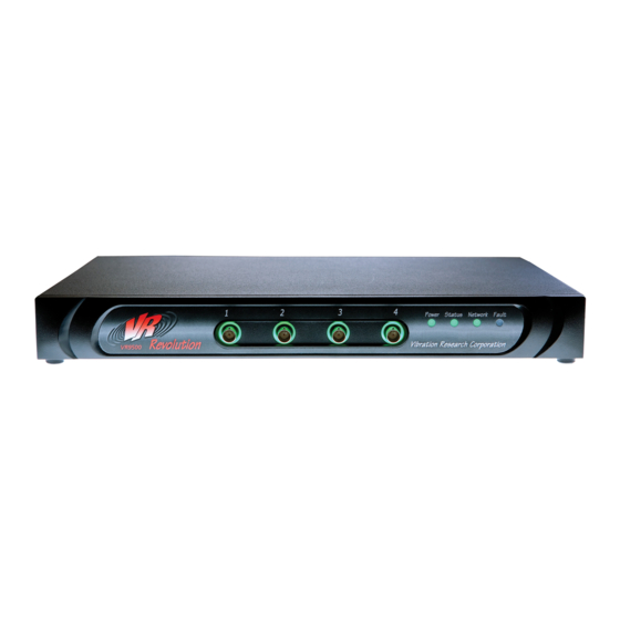
Troubleshooting & Diagnostics Front Panel LED POWER LED A power LED is located on the VR9500 front panel. The following table describes the power supply status LED indications: LED Color Description Green solid The switch (on rear of the VR9500) is turned on. - Page 27 STATUS LED A status LED is located on the VR9500 front panel. The following table describes the status LED indications: LED Color Description VR9500 is faulted. Green solid VR9500 is faulted. VR9500 is operating normally. A brief flash off once every second (mostly on with a brief flash off) indicates the box is connected to VibrationVIEW and is active.
- Page 28 Contact Vibration Research for assistance. CHANNEL LED On the VR9500 front panel, there is a channel LED around each of the four input channels. The following table describes the channel LED indications. The channel LED provide connection status of integrated electronics piezo electric (IEPE) accelerometers such as those sold under the Integrated Circuit Piezoelectric (ICP) and IsoTron trade names.
- Page 29 Rear Panel LED ETHERNET LED Color Description Left LED Green solid Link is active. Green flashing Link active and network activity. Right LED Amber solid 1000BT link is active. 100BT link is active and network activity. INTERBOX OPTION LED Color Description Green Hardware link is active.
-
Page 30: Warranty
Warranty Vibration Research Corporation warrants the hardware to be free of defects in materials and workmanship for a period of three (3) years from your original date of purchase. This warranty shall be extended as long as you agree to remain under a support agreement with Vibration Research Corporation;...
Need help?
Do you have a question about the VR9500 and is the answer not in the manual?
Questions and answers