Advertisement
Quick Links
Advertisement

Related Manuals for Vibration Research VR10500


Summary of Contents for Vibration Research VR10500
- Page 2 Notes, Notices, and Cautions © 2021 Vibration Research Corporation is a registered trademark in the United States and other countries. Information in this document is subject to change without notice. Document last revised Wednesday, March 24, 2021 - Jenison, Michigan.
-
Page 3: Table Of Contents
Table of Contents VR10500 Hardware Manual ................. 1 Hardware Overview ................. 4 Capabilities & Specifications ................. 6 Installation ................. 9 Connection ................. 13 Remote I/O ................. 21 Maintenance ................. 22 Troubleshooting & Diagnostics ................. 27 Warranty... -
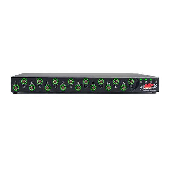
Page 5: Hardware Overview
Hardware Overview Front and Back Panel Inputs/Outputs support@vibrationresearch.com... - Page 6 · The rear panel has an interbox port for loop synchronization of multiple VR10500 units. Loop sync can be completed with hardware or software clocks. Hardware clocks via interbox connection are only recommended for systems with more than 48 input channels.
- Page 7 The DB37 connector can also support a tachometer. System Ventilation Fan The VR10500 has one fan for system ventilation. Make sure the fan and vent openings remain unobstructed to allow for proper airflow. support@vibrationresearch.com...
-
Page 8: Capabilities & Specifications
Capabilities & Specifications Item Check List The following items are included with the VR10500: · VR10500 I/O · AC power cable · Drive cable · Network (Ethernet) cable · Rack-mount kit for installation · Software CD · VibrationVIEW software manual VR10500 General Specifications ·... - Page 9 Environmental Specifications TEMPERATURE Operating: 35° to 122°F (2° to 50°C) Storage: -40° to 185°F (-40° to 85°C) Humidity: Up to 95% Relative Humidity, Non-Condensing Altitude: Up to 3,000m MSL (9,842ft) VIBRATION Random: MIL-PRF-28800F, Class 3 Shock: MIL-PRF-28800F, Class 3 support@vibrationresearch.com...
-
Page 10: Installation
Make sure the VR10500 is not exposed to radiators or heat sources. · Make sure the cooling vents are not blocked. · Do not push foreign objects into the VR10500 as it may cause a fire or electric shock. · Use the VR10500 with approved equipment only. - Page 11 Site Requirements The VR10500 can be mounted on a standard equipment rack or placed on a tabletop. Before installing the VR10500, verify that the site selected for the device meets the following site requirements: · Power — The VR10500 is installed within 5ft (1.5m) of a grounded and easily accessible outlet 220/110VAC, 50/60Hz.
- Page 12 Installation CONTINUED Installing on a Flat Surface The surface must be able to support the weight of the VR10500 and its cables. · Set the VR10500 on a flat surface; leave 2in (5.08cm) on each side and 5in (12.7cm) at the back.
-
Page 13: Connection
No operator settings are required for voltage configuration. · After connecting the VR10500 to a power source, confirm that the device is connected and operating correctly by examining the LEDs on the front panel. ·... - Page 14 CAUTION: The terminals on the unit should only be connected to passive load transducers or source transducers that apply no more than 10V to the circuit that originates from the VR10500 (or a value that equates to no more than 33Vac RMS/46.7V peak or 70Vdc total on the circuit).
- Page 15 CAUTION: Terminals provided on the unit should only be connected to passive load transducers or source transducers that apply no more than 10V to the circuit that originates from the VR10500 (or a value that equates to not more than 33Vac RMS /46.7V peak or 70Vdc total on the circuit).
- Page 16 VR Mobile: To connect the VR10500 to VR Mobile for remote monitoring, the VR10500 must be connected to the same network as the smart phone or tablet running the application. The smart phone/tablet serves as the user interface display following connection and can be used to check system configuration and configure live analyzer.
-
Page 17: Remote I/O
CAUTION: Terminals provided on the unit shall be connected only to passive load transducers or source transducers that apply no more than 10V to the circuit that originates from the VR10500 (or a value that equates to not more than 33Vac RMS/46.7V peak or 70Vdc total on the circuit). - Page 18 This interface uses a standard DB37 connector and an AMP 5747375-2 (or equivalent) mating connector. The pinout on the back of the VR10500 is displayed below. AUX INPUTS The eight AUX inputs can be used to read an analog signal up to ±12V at 16-bit resolution or a digital TTL signal.
- Page 19 Input signals in this configuration must be greater than 2.2V to ensure they are registered high and less than 0.6V to ensure they are registered low. Input signals may be up to 1MHz. The VR10500 supports quadrature decoding by using both tachometer inputs simultaneously.
- Page 20 5 to 8. The two AUXPWR groups may be powered independently of each other. Exceeding +26VDC on the AUX power interfaces may permanently damage the VR10500. For example, AUX outputs 1 to 4 could be configured for +12VDC operation by...
- Page 21 NOTE: After the voltage on AUXPWR_A or AUXPWR_B exceeds ~15VDC, a quiescent current of 25mA max will be drawn from the external power source. support@vibrationresearch.com...
- Page 22 Reference for AUX outputs, AUX Pow er, Tach Ground Emergency ESTOP_IN Used w ith ESTOP_OUT STOP IN Analog AGND Reference for AUX inputs Ground Analog AGND Reference for AUX inputs Ground Analog AGND Reference for AUX inputs Ground VR10500 Hardware Manual...
- Page 23 Remote I/O CONTINUED Analog AGND Reference for AUX inputs Ground Analog AGND Reference for AUX inputs Ground Analog AGND Reference for AUX inputs Ground Analog AGND Reference for AUX inputs Ground Analog AGND Reference for AUX inputs Ground Auxiliary AUXPWR_A Pow er - External pow er (up to +24VDC) for AUX outputs 1-4 Group A...
- Page 24 Vibration Research if you are interested in this functionality. Digital Output The digital output interface on the back panel of the VR10500 provides an additional two drive outputs that can connect to the digital input of an amplifier or digital to analog converter module.
-
Page 25: Maintenance
· The VR10500 is protected by fuses between the power cord and power switch. The power cord must be removed to replace the fuses. Replace the main fuses with the same type (usually a Bel Fuse 5ST 2.5-R) to maintain protection against overheating, hardware damage, and possible fire. -
Page 26: Troubleshooting & Diagnostics
Troubleshooting & Diagnostics Front Panel LED POWER LED A power LED is located on the front panel of the VR10500. The following table describes the power supply status LED indications: LED Color Description Green solid The switch on rear of the VR10500 is turned on. - Page 27 Troubleshooting & Diagnostics CONTINUED STATUS LED A status LED is located on the front panel of the VR10500. The following table describes the status LED indications: LED Color Description VR10500 is faulted. Green solid VR10500 is faulted. Green flashing VR10500 is operating normally.
- Page 28 FAULT LED A fault LED is located on the front panel of the VR10500. The following table describes the fault LED indications: LED Color Description No faults. Red solid Fault detected. Red flashing Fault detected. If the fault light is continuously on and the status light is continuously off, turn the power off and back on to reset the unit.
- Page 29 Troubleshooting & Diagnostics CONTINUED Rear Panel LED ETHERNET LED Color Description Right LED Green solid Link is active. Link is active and network Green flashing activity. Left LED Amber solid 1000BT link is active. support@vibrationresearch.com...
- Page 30 INTERBOX LED The high channel count sync interface option (also known as interbox) allows for loop synchronization of multiple VR10500 units. Loop synchronization can be performed with the Ethernet network or the interbox option. The interbox option provides tighter synchronization than Ethernet and will provide additional high channel count capabilities in the future.
-
Page 31: Warranty
Warranty Vibration Research Corporation warrants the hardware to be free of defects in materials and workmanship for a period of three (3) years from your original date of purchase. This warranty shall be extended as long as you agree to remain under a support agreement with Vibration Research Corporation;...
Need help?
Do you have a question about the VR10500 and is the answer not in the manual?
Questions and answers