Table of Contents
Advertisement
Quick Links
Advertisement
Table of Contents

Related Manuals for ImpulseRadar PinPointR


Summary of Contents for ImpulseRadar PinPointR
- Page 1 PinPointR User manual ImpulseRadar PinPointR User Manual V1.5.1...
-
Page 2: Table Of Contents
Data viewing and adjustment ......................20 Markers ............................. 22 Generate PDF Summery and KMZ file ....................23 Restoring missed traces ........................23 Multi-line project ........................... 23 GPS-projects ..........................27 Viewing files ............................27 ImpulseRadar PinPointR User Manual V1.5.1 Page 2 (36) - Page 3 Note on survey speed and settings ....................27 Appendix A – Specifications ........................29 Appendix B – File-formats ........................30 Appendix C – GPS ..........................33 Appendix D – Regulatory notices ......................34 ImpulseRadar PinPointR User Manual V1.5.1 Page 3 (36)
-
Page 4: About This Manual
GPS mounting kit make the system suitable for different kind of locating and mapping applications. For information on other applications and/ or configurations, please contact your local ImpulseRadar representative, or contact our sales team at sales@impulseradar.se This manual is structured as follows: •... -
Page 5: Hardware Overview
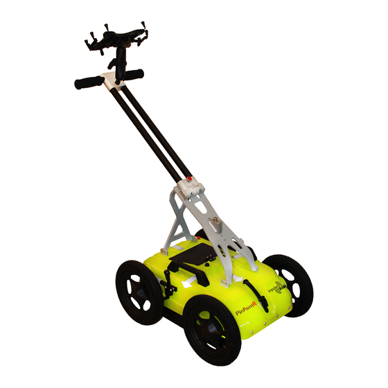
PinPointR 400 MHz and 800 MHz The PinPointR is a push-cart system supported by several accessories, as shown in Figure 1 below. Figure 1 System overview Data collection is managed over an Ethernet Wi-Fi link and a suitable Android device running the ImpulseRadar ViewPoint App (ViewPoint). -
Page 6: Connector Panel
Battery The PinPointR is powered via a removable and rechargeable Li-ion battery, which is a nominal 8.7 Ah/ 96.57 Wh, providing approximately 7-hours of continuous operation. Note: ImpulseRadar Li-ion batteries are approved according to UN38.3 and can, therefore, be safely hand-carried on passenger aircraft or shipped by air cargo. -
Page 7: Push-Cart
Figure 3 Exchange the battery Push-cart The PinPointR push-cart allows the GPR unit to be manoeuvred easily over a range of surfaces. It incorporates several useful features including a height-adjustable tray for the GPR unit itself, as well as a foldable handle assembly, and a foot brake. - Page 8 Figure 4 PinPointR push-cart features The PinPointR push-cart incorporates a foldable handle assembly, so when the system is not in use, it can be folded for easier storage and transportation, as shown above in Figure 4. When unfolded for use, the handle assembly is fixed in place using a retaining screw. Depending on the model you have, this screw may be a threaded steel bolt that is fully removable, or on newer models, the screw is held in place within the handle assembly by a spring mechanism, as shown in Figure 5.
-
Page 9: Gpr Unit Removal Procedure
Figure 7. For this purpose, a spare o-ring is cable-tied to the encoder cable under the push-cart hood. Note: when refitting the wheel, use blue Loctite or equivalent to help secure the M6 retaining screw. ImpulseRadar PinPointR User Manual V1.5.1 Page 9 (36) -
Page 10: Gps Mounting Kit
RS232 serial link is established between the external GPS receiver and the GPR unit. Refer to Appendix C – GPS for a description of the external GPS cable and pin-outs. Figure 8 GPS mounting kit assembly ImpulseRadar PinPointR User Manual V1.5.1 Page 10 (36) -
Page 11: Software Overview
The PinPointR is set-up and controlled wirelessly via the ImpulseRadar ViewPoint App once installed on a suitable Android Tablet (“Device”). While it is feasible to operate the PinPointR using an Android Smartphone, it is not recommended due to the small screen size, which will affect your ability to identify and mark targets in the field. -
Page 12: Avoiding Wi-Fi And Connectivity Issues
‘auto-connect’ setting enabled, then the Device will attempt to connect to that wireless network instead of the GPR unit. Hence the importance of deactivating ‘auto-connect’ on saved networks. ImpulseRadar PinPointR User Manual V1.5 Page 12 (36) -
Page 13: Multiple Devices
If your Device has an internet connection, you can download the ViewPoint installation file directly from the Resource area of the ImpulseRadar website at https://impulseradargpr.com/resources. Alternatively, if your Device incorporates a USB-A port, you can install ViewPoint directly by connecting ImpulseRadar PinPointR User Manual V1.5... -
Page 14: Wi-Fi Pairing And Password Initialization
1. Switch on the PinPointR system 2. On your Device, navigate to Settings > Wi-Fi > and look for the PinPointR system ID, which will appear as ‘CO_XXXXXXXX’ (where XXXXXXXX is the serial number of the system) 3. Select this Wireless Access Point (WAP), and you will be prompted to enter the password, which is ‘impulseradar’... -
Page 15: Using Viewpoint
Note: Generally, the ViewPoint version number can be found on the start screen below the ImpulseRadar logo, as shown in Figure 13. However, this may also appear to the right of the logo, depending on the Device or its screen orientation. -
Page 16: Description Of Gpr Unit Settings
• Wheels – defines the type of wheel connected to the system for distance measurement. The standard wheel is the Direct Drive Cart. PinPointR users that have the older Belt Drive Cart need to select that type of wheel encoder manually. -
Page 17: Description Of User Preferences
Dual-View, Reference Line, or GPS projects, as shown in Figure 16. Regardless of the project type, you must select a project folder to which the Figure 16 Project modes ImpulseRadar PinPointR User Manual V1.5 Page 17 (36) -
Page 18: Running A Single Line Project And Associated Functionality
Figure 19 below describes additional functionality available during and after a survey, even if ViewPoint is disconnected from the GPR unit. When ViewPoint is used in standalone, all functions except the back-up cursor and crosshair lock are available. ImpulseRadar PinPointR User Manual V1.5 Page 18 (36) -
Page 19: Gps-Symbols And Function
GPS or an external GPS receiver can lock onto a suitable number of satellites. The GPS symbol will change colour and style according to GPS status, as defined below in Figure 20. By pressing the GPS-symbol you can see a static view of the current satellites and coordinates. ImpulseRadar PinPointR User Manual V1.5 Page 19 (36) -
Page 20: Wheels
RTK-GPS is run separately from the GPR unit; for example, in a multi-sensor set-up. Wheels The push-cart wheel is the default selection for the PinPointR system. Any other use of the system will require a new wheel calibration. - Page 21 Android screen gestures. To zoom in, pinch and expand two fingers; pinch and close two fingers to zoom back out. The current zoom level can be seen in the bottom-left corner of the footer ImpulseRadar PinPointR User Manual V1.5 Page 21 (36)
-
Page 22: Markers
Marker info window is open by simply tapping the trash icon. When a marker is assigned, an automatic screenshot of the radar data with the marker assignment is saved for use in the PDF Field Summary report and KMZ file. ImpulseRadar PinPointR User Manual V1.5 Page 22 (36) -
Page 23: Generate Pdf Summery And Kmz File
From the project start screen, as shown in Figure 26, you will be prompted to enter a project name and the distance between each profile. Once registered, press the ‘Start the Project’ button to continue. ImpulseRadar PinPointR User Manual V1.5 Page 23 (36) - Page 24 Profiles are gathered in straight lines, perpendicular to the reference line, and a reference- marker is placed within the GPR data every time the reference line is crossed, as illustrated below in Figure 27 and Figure 28. Figure 27 Layout of a reference-line project ImpulseRadar PinPointR User Manual V1.5 Page 24 (36)
- Page 25 “right” of the first profile. Make sure that the push-cart is stopped on top of the Reference line, arrows on the Cart hood must match the Reference line. The profile continues to be collected until reaching point 3, at which the stop button is pressed. ImpulseRadar PinPointR User Manual V1.5 Page 25 (36)
- Page 26 RL-project. On import, the end of profile 1 constitutes an artificial reference line. If considered before a survey, a DV-project may be used for post-processing and interpretation just as an RL-project. ImpulseRadar PinPointR User Manual V1.5 Page 26 (36)
-
Page 27: Gps-Projects
As the name suggests, this project type requires GPS for positioning. For accurate mapping, to survey or map grade, RTK-GPS is required. That said, it is possible to run a GPS-project using the PinPointR’s internal GPS, but this will lack the precision necessary for accurate interpretation. GPS projects using the internal GPS can be used for a field sketch with the Google Mapping capability and accuracy will vary depending upon the location and time of day of the survey. - Page 28 Finally, the PinPointR, like all GPR systems, will lose lateral-resolution at depth. This decreases the demand on the point interval, so no need to collect data any denser than necessary, concerning the targets you want to resolve.
-
Page 29: Appendix A - Specifications
Appendix A – Specifications ImpulseRadar products are under continuous development, and we reserve the right to change specifications at any time and without prior notice. You may verify product specifications at any time by contacting our headquarters at; support@impulseradar.se PinPointR... -
Page 30: Appendix B - File-Formats
(counting from 1) and XXX is a profile running number (counting from 1) ¹ Table 1 ImpulseRadar file types and descriptions ¹ file names are padded with zeros to replace ‘X’, e.g., <project name>_001_AYY.iprb Files/information stored in the system... - Page 31 Profile Data File This is a binary file. PinPointR can create data files with a 16-bit or 32-bit data format (see the field “DATA VERSION” in the header file). Samples are stored as signed 16-bit or 32-bit integers. The traces are stored sequentially.
- Page 32 1.201 extern gps ml outside_001_0 1.201 extern gps ml outside_001_1 1.201 extern gps ml outside_002_0 1.201 extern gps ml outside_002_1 1.201 extern gps ml outside_003_0 1.201 extern gps ml outside_003_1 </profiles> TYPE: 3 SEPARATION: 0.25 ImpulseRadar PinPointR User Manual V1.5 Page 32 (36)
-
Page 33: Appendix C - Gps
Figure 31 External GPS diagram and wiring arrangements ImpulseRadar PinPointR User Manual V1.5 Page 33 (36) -
Page 34: Appendix D - Regulatory Notices
RSS GEN : This Device contains license-exempt transmitter(s)/receiver(s) that comply with Innovation, Science and Economic Development Canada’s license-exempt RSS(s). Operation is subject to the following two conditions: (1) This Device may not cause interference. ImpulseRadar PinPointR User Manual V1.5 Page 34 (36) - Page 35 For your convenience, the information required by the FCC is indicated on the next page, please print and fill in the information and put the letter in the mail. FCC will respond with confirmation of coordination. Date: __________________ ImpulseRadar PinPointR User Manual V1.5 Page 35 (36)
- Page 36 __________________________________________________________________________________ CONTACT INFORMATION [CONTACT NAME AND PHONE NUMBER]: __________________________________________________________________________________ __________________________________________________________________________________ __________________________________________________________________________________ AREA OF OPERATION [COUNTIES, STATES OR LARGER AREAS]: __________________________________________________________________________________ __________________________________________________________________________________ __________________________________________________________________________________ __________________________________________________________________________________ FCC ID (tic the box) CrossOver 4080: 2ALZQ-CO4080 ImpulseRadar PinPointR User Manual V1.5 Page 36 (36)
Need help?
Do you have a question about the PinPointR and is the answer not in the manual?
Questions and answers