Table of Contents
Advertisement
Quick Links
66
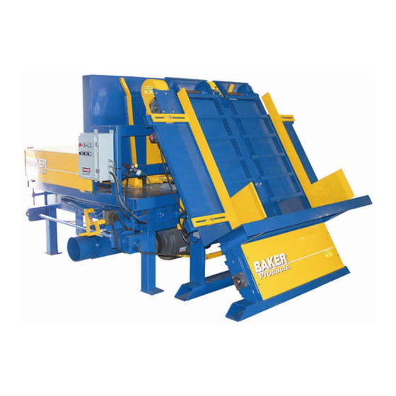
Equipment Photo
T
M
T
M
B
a
k
e
r
D
o
u
b
l
e
N
o
t
c
h
e
r
B
a
k
e
r
D
o
u
b
l
e
N
o
t
c
h
e
r
U
s
e
r
M
a
n
u
a
l
U
s
e
r
M
a
n
u
a
l
Ellington Industrial Supply, Inc.
P. O. Box 128
Ellington, Missouri 63638 USA
Web site:
www.baker-online.com
E-mail:
info@baker-online.com
Phone: (573) 663 – 7711 Fax: (573) 663 – 2787
Advertisement
Table of Contents

Related Manuals for Baker Double Notcher

Summary of Contents for Baker Double Notcher
- Page 1 Equipment Photo Ellington Industrial Supply, Inc. P. O. Box 128 Ellington, Missouri 63638 USA Web site: www.baker-online.com E-mail: info@baker-online.com Phone: (573) 663 – 7711 Fax: (573) 663 – 2787...
-
Page 2: Table Of Contents
Inspection and Preventative Maintenance Checklist Checking Cutters Cutter Inserts Replacing 2-sided Carbide Inserts Replacing Radius End Cutter Disc Inserts Replacing Belts Air Assembly PARTS AND SERVICE 30-32 Service Contact Information Serial Number Location Baker Double Notcher - Rev 2, 09/07; WWW.BAKER-ONLINE.COM... -
Page 3: Introduction
For safety reasons, and for your own best use of the Baker Double Notcher, we insist that you read this manual fully, and constantly review and refer back to it as necessary. -
Page 4: Definition Of Terms
Descrambler A conveyor system that arranges and positions boards for sequential feeding into a processing station, such as the Baker double notcher Edge Guide A straight edge that is used to guide a 3-sided flitch along a piece of material... -
Page 5: Manual Contents Notice
• 28 in up to 76 in (71 cm to 193 cm) standard Notch Depth • 0” (0 mm) min. • 3” (76 mm) max. Notch Length • 9” (229 mm) standard Baker Double Notcher - Rev 2, 09/07; WWW.BAKER-ONLINE.COM... -
Page 6: Warranty
CEO or Sales Manager of Baker Products. Our one (1) year warranty period covers all items built at our manufacturing facilities including structural frame, cowlings, doors, shafting, dust chutes and guards. -
Page 7: Defective Parts
Power Source:…………..…………………….…………………………………… Dust Removal: ….……………………………………………………………….… Ellington Industrial Supply, Inc. P. O. Box 128 Ellington, Missouri 63638 USA Web site: www.baker-online.com E-mail: info@baker-online.com Phone: (573) 663 – 7711 Fax: (573) 663 – 2787 Baker Double Notcher - Rev 2; 09/07 WWW.BAKER-ONLINE.COM... -
Page 8: Rules For Safe Operation
No list of safety expectations can ever be complete as every work environment is as different as are the people operating the equipment. Always keep safety as your highest priority and always use this machine with caution and respect. Baker Double Notcher - Rev 2, 09/07; WWW.BAKER-ONLINE.COM... -
Page 9: Control Of Hazardous Energy - (Lockout / Tagout)
1. Failure to stop equipment 2. Failure to disconnect from a power source 3. Failure to dissipate (bleed, neutralize) residual energy 4. Accidental re-starting of equipment 5. Failure to clear work areas before re- starting Baker Double Notcher - Rev 2, 09/07; WWW.BAKER-ONLINE.COM... -
Page 10: Machine Safety Decals
Machine Safety Decals ** Adhere to ALL Safety Warnings! ** Baker Double Notcher - Rev 2, 09/07; WWW.BAKER-ONLINE.COM... -
Page 11: Machine Features
MACHINE FEATURES We want to highlight the unique and special features of the Baker Double Notcher. Heavy-duty steel construction Powerful electric motors, one per cutter head Air driven material “pusher” with electrical controlled travel limit switches Infeed un-scrambler keeps material flow steady while reducing labor... -
Page 12: Set-Up
Efficient dust and chip removal requires a minimum of 3,600 CFM suction at the machine dust removal chute. This is an end user/owner responsibility. Note: Failure to provide proper vacuum or suction may result in damage to machine or operations personnel. Baker Double Notcher - Rev 2, 09/07; WWW.BAKER-ONLINE.COM... -
Page 13: Operator Training
Operator Machine All five (5) of these listed items together make Guards up the safety system. Failure of any one of these factors will increase accident potential. Devices Instructions ’ ’ Baker Double Notcher - Rev 2, 09/07; WWW.BAKER-ONLINE.COM... -
Page 14: Operation
• Jog On / Off – When switched on, the pusher is held in the starting or retracted position. Note: This function is used to allow the operator to remove jammed boards while the pusher mechanism is held back to clear. Figure 14 Baker Double Notcher - Rev 2, 09/07; WWW.BAKER-ONLINE.COM... -
Page 15: Adjusting The Table Top
Re-position the holding bolts and tighten the two (2) adjustment nuts located on each of the four corners – eight (8) total. Table Top Adjustment Nuts Notch Location Adjusting Crank Table Height Adjustor Crank Holding Bolt Figure 15 Baker Double Notcher - Rev 2, 09/07; WWW.BAKER-ONLINE.COM... -
Page 16: Adjusting For Notch Depth
(Figure 16). Weight Bars Figure 16 Baker Double Notcher - Rev 2, 09/07; WWW.BAKER-ONLINE.COM... -
Page 17: Adjusting For Material Length
Note: The guide rails should be set close to the edge of the material, but not disrupt material flow or create resistance. Weight Bars Hopper Guide Rails Figure 17 Baker Double Notcher - Rev 2, 09/07; WWW.BAKER-ONLINE.COM... -
Page 18: Adjusting For Material Height
Lower and latch the two (2) top protective panels and raise and latch the two (2) protective side panels. Note: These steps must be repeated every time stringer/board height needs to be changed. Shaft Holding Nuts Weight Bars Side Panel Shaft Holding Nuts Figure 18 Baker Double Notcher - Rev 2, 09/07; WWW.BAKER-ONLINE.COM... -
Page 19: Adjusting The Width Of The Material Bin Hopper
For example, if the width of the material is 1 ½” (38mm), set the bin width or depth to 2” (50mm). Feed Bin Hopper Adjuster Nuts Back Stop Figure 19 Baker Double Notcher - Rev 2, 09/07; WWW.BAKER-ONLINE.COM... -
Page 20: To Begin Processing Material
When the wood falls below a certain level, the conveyor will start feeding the hopper again automatically. Note: Also always remember to raise the table when shutting off the motors. Figure 20 Baker Double Notcher - Rev 2, 09/07; WWW.BAKER-ONLINE.COM... -
Page 21: Proximity Switches
Failure to do so may result in serious injury. The proximity switches should be positioned no more than ¼” (6mm) from the material. LED light Adjustment Screw Switch 4 Switch 2 Switch 3 Figure 21A Close Up View of Proximity Switch Switch 1 Figure 21 Baker Double Notcher - Rev 2, 09/07; WWW.BAKER-ONLINE.COM... -
Page 22: Pusher Speed Adjustment
Note: The function select dial is set at the factory to “On Delay” and should never have to be adjusted. LED light Number select buttons (one under each number column) Figure 22 Baker Double Notcher - Rev 2, 09/07; WWW.BAKER-ONLINE.COM... -
Page 23: Pusher Stroke
You want just enough of an open area to allow material to drop into position. Stroke Front Limit Adjuster Arm Switch Angle Adjustors Rear Limit Switch Stroke Adjuster Arm Angle Adjustors Figure 23 Direction of Pusher Baker Double Notcher - Rev 2, 09/07; WWW.BAKER-ONLINE.COM... -
Page 24: Clearing Lumber Jams
Return and latch the two (2) protective top panels into their proper place. Remove lock-out / tag-out device and turn the JOG switch to the OFF position. When ready, resume normal operation. Figure 24 Baker Double Notcher - Rev 2, 09/07; WWW.BAKER-ONLINE.COM... -
Page 25: Maintenance
Grease the pillow block bearings on the cutter head shafts. We recommend JT-6 grease (no more than 5 pumps). Monthly Grease the 1” bearings on the descrambler deck. JT-6 grease (no more than 5 pumps). Baker Double Notcher - Rev 2, 09/07; WWW.BAKER-ONLINE.COM... -
Page 26: Checking Cutters
Install new carbide insert against freshly cleaned seat. Replace chip breaker wedge block. Retighten socket head cap screw. Carbide Insert Seat Wedge Block Figure 26 Baker Double Notcher - Rev 2, 09/07; WWW.BAKER-ONLINE.COM... -
Page 27: Replacing Radius End Cutter Disc Inserts
Note: We recommend rotating the radius end cutter disc inserts approximately 1/3 of its diameter every 2 weeks and replace them after 3 rotations. Washer Hex head bolt Radius end cutter disc insert Figure 27 Baker Double Notcher - Rev 2, 09/07; WWW.BAKER-ONLINE.COM... -
Page 28: Replacing Belts
(4 total) Belt tension should be “taut” Belt tension should be “taut” with no more than 1/2” with no more than 1/2” deflection in the belt deflection in the belt Figure 28 Baker Double Notcher - Rev 2, 09/07; WWW.BAKER-ONLINE.COM... -
Page 29: Air Assembly
Air Assembly Notcher 1/2” incoming main air supply line Solenoids Solenoids Air Muffler Air Muffler Exhausts Exhausts Figure 29 Operate at 90 psi Descrambler 1/2” incoming air supply connection Figure 29A Baker Double Notcher - Rev 2, 09/07; WWW.BAKER-ONLINE.COM... -
Page 30: Parts And Service
1/4” air quick plug 121006 121007 #50 chain roller #50 chain connector link 131014 131039 Sprocket Morse torque Sprocket 5012 x 3/4” limiter 131040 131042 Sprocket 50B12F x 1” Sprocket 50BB13H x 1/2” idler Baker Double Notcher - Rev 2, 09/07; WWW.BAKER-ONLINE.COM... - Page 31 101006 101014 Bearing 1-1/2” 4 bolt flange Bearing 1” 2 bolt flange; 17/32” bolt hole 101025 101080 Bearing 2-3/16” pillow block Bearing 1-1/4” 2 bolt flange; 5/8” bolt hole Baker Double Notcher - Rev 2, 09/07; WWW.BAKER-ONLINE.COM...
-
Page 32: Service Contact Information
The model and serial number are located on the front side of the machine near the operator station. Please refer to your serial number and model number when speaking to a service technician or ordering replacement parts. Baker Double Notcher - Rev 2, 09/07; WWW.BAKER-ONLINE.COM...
Need help?
Do you have a question about the Double Notcher and is the answer not in the manual?
Questions and answers