Table of Contents
Advertisement
Quick Links
Advertisement
Table of Contents

Subscribe to Our Youtube Channel
Related Manuals for Siemens SION


Summary of Contents for Siemens SION
- Page 1 7.2 kV – 17.5 kV, 16 kA – 40 kA 24 kV, 16 kA – 25 kA 12 kV – 17.5 kV, 31.5 kA for generator switching applications OPERATING INSTRUCTIONS Order no.: 9229 0025 176 0E Version: 09.2021 en © Siemens AG 2021. All rights reserved.
-
Page 2: Service
Service Contact partner for Siemens service (24 h): • Telephone: +49 180 524 7000 • Fax: +49 180 524 2471 • Email: support.energy@siemens.com • Or via any local Siemens representative 9229 0025 176 0E 2021-11-15... -
Page 3: Table Of Contents
Attachment in the switching cubicle ........................39 Earthing ................................49 Connecting low voltage ............................. 50 Electrical connection of the main conductors ....................53 ® Inserting and racking the SION withdrawable circuit-breaker ................. 64 Operation ................................ 69 Commissioning ..............................69 First closing operation ............................70 Closing ................................ -
Page 4: List Of Abbreviations
List of abbreviations ABS-PC mixture Mixture of acrylonitrile butadiene styrene (ABS) and polycarbonate (PC) BGBl Bundesgesetzblatt (German Federal Law Gazette) Closed-Open Deutsches Institut für Normung (German Institute for Standardisation) International Electrotechnical Commission Open NC Contact Pole-centre distance NO Contact StrlSchG Radiation Protection Act StrlSchV Radiation Protection Ordinance... -
Page 5: For Your Safety
For your safety For your safety The operating instructions are an integral part of the switching device and contain all the information for commissioning and use. The operating instructions must be read completely, the instructions contained must be followed and the warnings must be observed. Smooth and safe operation of this switching device requires proper transport and storage, professional installation and assembly, as well as careful operation and maintenance. -
Page 6: Manufacturer's Product Liability
Product liability claims are upheld only if the replacement of the purchased spare parts is performed by personnel that have been trained and certified by Siemens. The manufacturer’s product liability shall be excluded if at least one of the following criteria applies: •... - Page 7 22). Irreparable damage Note ® Material damage due to incorrect operation! If the SION vacuum circuit-breaker is triggered manually with the cover removed and the mechanical interlock actuated, the operating mechanism of the vacuum circuit-breaker will be irreversibly dam- aged.
-
Page 8: Type Approval According To The Radiation Protection Act (Formerly German X-Ray Ordinance)
For your safety Flammable packaging Note Observe fire load! The packing materials are not protected against open flames and may burn. During storage, attention must be paid to the fire load of the packing materials and the quantity must be calculated according to the storage conditions. Damaged components Note Damaged components! In the case of damage, such as breaks, cracks, flaking,... -
Page 9: Transport, Storage And Packing
Transport, storage and packing Transport, storage and packing Transport Lifting gear WARNING Unsuitable lifting gear! Incorrectly dimensioned fixing gear or incorrectly adjusted lifting gear may cause the transport unit to fall down. • Do not stand below suspended loads. • Select lifting gear, transportation and fixing gear according to the weight of the transport unit, including any packing, such as transport pallets. -
Page 10: Unpacking
Transport, storage and packing After receipt of delivery: Checking the transport • Check the transport unit for damage. unit • Major damage must be documented photographically. • Ensure that any damage to the transport unit is confirmed by the transport com- pany in writing. - Page 11 Send it back in its original transport unit (see “Reuse of transport unit”, page 13). Fig. 3 Example – unpacking the fixed mounting ver- Fig. 4 Example – unpacking version with withdrawa- sion ble part Transportation to the • Remove all tensioning belts and bits of fastening wood.
- Page 12 Transport, storage and packing Fig. 5 Transporting by crane hook Fig. 6 Transporting on snap hooks 1) Diameter of the hook cross-section max. 19 mm 2) Opening width of the hook min. 18 mm Fig. 7 Transporting, only for 31.5 kA with distance Fig.
-
Page 13: Reuse Of Transport Unit
Attach the supplementary equipment. • Close the box securely. • Before returning to the factory, ask the responsible Siemens representative for a returned products number (see also “Service”on page 2). • When returning a vacuum circuit-breaker, always specify the type and serial number (see “Name plate”, on page 34). - Page 14 Transport, storage and packing Blank page 9229 0025 176 0E 2021-11-15...
-
Page 15: General Information
IEC 62271-1:2017 and VDE 0671-1) is maintenance-free for up to 10 000 operating cycles. 30 000 operating cycles require maintenance work that must only be performed by personnel trained by Siemens (see also “Maintenance” on p. 73). ® Intended use... -
Page 16: Scope Of Delivery
General information Scope of delivery Delivery includes: • SION® vacuum circuit-breaker • or SION® vacuum circuit-breaker on withdrawable part • Supplementary equipment with 10-pole plugs for • 20-pole connector strip or • 30-pole connector strip • Operating instructions and unpacking instructions •... -
Page 17: Description
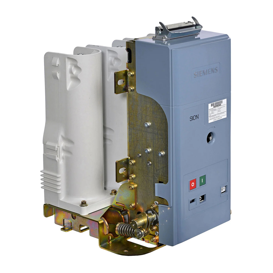
Description Description Design The images shown are examples; not all the variants of the vacuum circuit-breaker are shown here. Fig. 9 12 kV, 25 kA, 1250 A, operating mechanism Fig. 10 12 kV, 25 kA, 1250 A, pole side, without insu- side lating shells for system side Fig. - Page 18 Description Fig. 13 24 kV, 16–25 kA, 2500 A, operating mecha- Fig. 14 24 kV, 25 kA, 2500 A, pole side with with- nism side with withdrawable part drawable part, without insulating shells for system side Withdrawable part Pole contact plate 20.1 Cover Insulator...
- Page 19 Description Operating mechanism The operating mechanism contains all the electrical and mechanical components re- quired to close or open the vacuum circuit-breaker. Insulated operating rods transfer the switching movement to the pole assemblies. The operating mechanism is covered by the removable cover made from insulating material (20.1) or metal (20.2).
- Page 20 Description Secondary equipment Fig. 17 Open operating mechanism, example 12 kV, 25 kA, 1250 A Auxiliary switch (-S1) 54.6 Position switch (-S6), circuit-breaker tripping signal Low-voltage plug connector (-X0) (optional) (optional, not shown) Plug (Q0-X1.1, Q0-X1.2, Q0-X1.3) only when ordering the Closing spring 20-pole or 30-pole connector strip (not shown) 55.1...
- Page 21 Description Fig. 18 Open operating mechanism, example 17.5 kV, 31.5 kA, 2500 A Auxiliary switch (-S1) (optional, not shown) Low-voltage plug connector (-X0) (optional) Closing spring Plug (Q0-X1.1, Q0-X1.2, Q0-X1.3) only when ordering the 55.1 Spring state indicator 20-pole or 30-pole connector strip (not shown) 56.3 Position indicator CLOSED-OPEN 33.2...
- Page 22 3AX11 releases. For the permitted possi- ble combinations of the additional equipment as well as special designs, refer to cat- alogue HG11.02 or contact the competent Siemens agency. 9229 0025 176 0E 2021-11-15...
- Page 23 Description Motor (-M1) After the supply voltage is applied and if the closing spring is discharged, the motor starts immediately and is automatically deactivated internally after charging has taken place. For power consumption, see table Fig. 20. In the short charging time, the motor operates in the overload range.
- Page 24 Description Anti-pumping device (-K1) If simultaneous electrical CLOSE and OPEN commands are continuously applied to the vacuum circuit-breaker, it returns to the open position after being closed. The function of the anti-pumping device (-K1) means that the vacuum circuit-breaker remains there until the ON command is re-entered.
- Page 25 Description 1st shunt release (-Y1) In the case of the 1st shunt release (-Y1), the electrically fed tripping pulse is passed to the “OPEN” latch by means of a directly acting magnet armature, thus switch- ing off the vacuum circuit-breaker. The 1st shunt release (-Y1) is not designed for continu- ous operation and is terminated within the circuit-breaker via the auxiliary switch (-S1) at the factory.
- Page 26 Description Auxiliary switch (-S1) The auxiliary switch (-S1) is available for delivery in two versions: with 6 NO contacts or 12 NC contacts each. Contacts available on the customer’s premises – see cir- cuit diagram supplied. Fig. 26 Auxiliary switch (31) Power consumption Rated insulation voltage: AC/DC 250 V...
- Page 27 Description Circuit-breaker tripping signal (-S6) 3AX4206-0A The position switch (-S6) makes contact briefly when the vacuum circuit-breaker is opened by means of an elec- trical release. This contact can be used for a signal. Fig. 27 Circuit-breaker tripping signal (54.6) Low-voltage interface (-X0) Fig.
- Page 28 • for generator circuit-breaker SION : MLFB = B ® • for all other vakuum circuit-breaker SION MLFB = B with addition G39 2nd Shunt release (Fig. 30) Power consumption 300 W bis 370 W / VA (3AY1410-..) In the case of the 2nd shunt release (-Y2), the electrically fed tripping pulse is passed to the “OPEN”...
- Page 29 Description Transformer operated releases (-Y4), (-Y5) 3AX1102-.., (-Y6) 3AX1104-.. Fig. 32 Transformer operated release (51.3) Fig. 33 Transformer operated release (51.3) The transformer operated releases (-Y4), (-Y5) and (-Y6) consist of an energy store, an unlatching fixture and an electromagnetic system. If the tripping current is ex- ceeded (90 % of the transformer operated release’s rated current), the stored ener- gy mechanism is unlatched, thus initiating opening of the vacuum circuit-breaker.
- Page 30 Description Undervoltage release (-Y7) 3AX1103-.. Note Damage due to missing or incorrect series resistor! Operation without series re- sistor (-R1) can cause damage. The undervoltage release (-Y7) may only be operated with the supplied series resis- tor (-R1). For circuits (mechanical or electrical), the undervoltage release 3AX1103-.. must be connected to control voltage, as otherwise closing is not possible (see “Removing the transport block from the undervoltage release”, page 52).
-
Page 31: Interlocks
Description Heater (-R01) for condensation water protection (optional) The heater minimises condensation and corrosion of the vacuum circuit-breaker. To this end, the heater has to be connected to the supply voltage (see circuit diagram included with the delivery). WARNING Hot surfaces! Touching hot components can cause burns. - Page 32 Description 35 ±0.3 mm Fig. 37 Mechanical interlock Stroke in the OPEN switch position (min. 5 mm, max. 10 mm) Query or actuation component (cross-section max. 14 mm x 3 mm, actuation force min. 50 N, max. 450 N) c + d Refer to dimension drawing Sectional view View from below...
- Page 33 Description Key-operated interlock 3AX1437-.. (optional) If the vacuum circuit-breaker is equipped with a key-op- erated interlock, it is possible to mechanically prevent both manual closing and electrical closing (position switch -S5). To prevent the vacuum circuit-breaker from being man- ually or electrically closed, press and hold the OPEN pushbutton, until the key is turned to the CLOSED posi- tion (vertical).
-
Page 34: Name Plate
Made in Germany Classification E2, C2 and M2 for circuit- breakers according to the standard Fig. 40 Example – name plate Technical data ® Vacuum circuit-breaker SION Rated voltage U (at f 50/60 Hz) 17.5 Rated normal current I 800 – 3150 / 4000 800 –... - Page 35 Dimensions and weights The dimensions of the vacuum circuit-breaker can be taken from the relevant dimen- sional drawing. If needed, they can be obtained from your Siemens representative. The weight is indicated on the vacuum circuit-breaker name plate (see Fig. 40), or refer to the associated dimension drawing.
-
Page 36: Ambient Conditions
Description Ambient conditions Occasional condensation may occur under these ambient conditions. ® SION Vacuum circuit-breakers are suitable for use in the following climate classes according to IEC 60721-3-3:2019: +55 °C Class • Climatic ambient conditions: 131 °F • Biological ambient conditions: •... -
Page 37: Switching Times
Circuit diagrams The circuit diagrams for the vacuum circuit-breaker are compiled depending on your order. The corresponding circuit diagram book can also be downloaded from the following URL on the internet: https://support.industry.siemens.com 9229 0025 176 0E 2021-11-15... - Page 38 Description Blank page 9229 0025 176 0E 2021-11-15...
-
Page 39: Installation
Any warranty claims are lost in the event of such incorrect operation. ® Use suitable means to prevent the SION vacuum circuit-breaker from closing if the cover has been removed and the mechanical interlock has been actuated. - Page 40 Installation Removing and mounting covers Remove the covers to mount the fixing straps. Removing and mounting cover made from insulating material Fig. 47 Removing cover made from insulating materi- Fig. 48 Mounting cover made from insulating material Removing • Pull off both the engaging hooks of the cover (20.1) simultaneously. •...
- Page 41 Installation Removing and mounting metal cover 12 Nm Fig. 49 Removing metal cover – example Fig. 50 Mounting metal cover – example Removing • Loosen both upper M6 hexagonal bolts but do not unscrew them. • Unscrew the bottom four M6 hexagonal bolts with the contact washers. •...
- Page 42 Installation Mounting the cable outlet for the external cable harness (optional) A cable outlet (60) with fixing material is included in the supplementary equipment for the external cable harness mounted by the customer. The cable outlet serves to bundle and protect the cables coming from the low-voltage interface. Self-tapping screws are suitable for single use only.
- Page 43 Installation Mounting the system-side insulating shells System-side insulating shells (47) can be used to insulate the individual poles from each other if there is restricted terminal space. When using system-side insulating shells (47), you can use main conductors with a max.
- Page 44 Installation Fig. 56 Mounting the insulating shells Fig. 57 Engaging the insulating shells • Place insulating shell (47) onto the rib (arrow a) from the top at a slight angle. • Push the bottom part of the insulating shell (47) against the pole shell (46) until it engages audibly.
- Page 45 Installation mechanism (see “Connecting low voltage”, page 50). Fig. 60 Example with withdrawable part Installation of the fixed-mounted circuit-breaker on a vertical plane (optionally using fixing straps 3AX1411-6A) The framework or the frame must be made to suit the service conditions and have sufficient load-bearing capacity and stability.
- Page 46 Installation Mounting the protective plates (optional) The protective plates are metal sheets that separate the high-voltage area from the operating mechanism area and provide additional protection against the pressure wave in the event of an arc fault. The protective plates are accessories and depend on the design of the switching de- vice.
- Page 47 Installation Installation of the transparent insulating plate (addition E55 or E65, optional) The transparent protective plate is an accessory and depends on the design of the switching device. You can ask the manufacturer if mounting is possible. The transparent insulating plate (65) is required at a rated short-term power frequen- cy withstand voltage of 55 kV and 65 kV.
- Page 48 Installation Installation of the circuit-breaker shaft covers (optional) The circuit-breaker shaft covers are accessories and depend on the design of the switching device. You can ask the manufacturer if mounting is possible. A mounted circuit-breaker shaft cover prevents access to open moving parts and prevents injuries.
-
Page 49: Earthing
Installation Earthing Note ® If the SION vacuum circuit-breaker is installed in an earthed metal framework and is connected permanently and electrically conductive, no separate earthing is re- quired. Place serrated washers under the screw heads when fixing the vacuum circuit- breaker in this case. -
Page 50: Connecting Low Voltage
Installation Connecting low voltage Connect the low-voltage connection cables in the customer’s switchgear in such a way that safe operation as per the supplied circuit diagram is guaranteed. Low-voltage interface (-X0), 64-pole 3AX1134-.. For connection of the control cable, the standard version of the vacuum circuit-breakers is equipped with a 64-pole low-voltage interface (-X0). - Page 51 Installation Connecting the low voltage for the withdrawable part Fig. 73 Laying the cable harness Fig. 74 Laying the cable harness Laying the cable harness • Feed the cable harness of the withdrawable part with the plugs (-Q0) along the (see Fig.
- Page 52 Installation Removing the transport block from the undervoltage release Undervoltage release (-Y7) The vacuum circuit-breaker with an undervoltage release (-Y7) 3AX1103-.. is sup- available? plied with a transport block. • Remove the cover (see “Removing and mounting covers” page 40). •...
-
Page 53: Electrical Connection Of The Main Conductors
Installation Electrical connection of the main conductors Checking the vacuum circuit-breaker in the panel with applied high voltage is al- lowed only after full functionality has been determined (see “Commissioning”, on page 69). Preparing the contact surfaces Clean copper-plated and silver-plated connecting surfaces with a cloth; do not brush. - Page 54 28 ±1 38 ±1 28 ±1 44 ±1 only with additional active cooling (fc) SION generator circuit-breaker Fig. 81 Screw-in depths Mounting conductor bars For vacuum circuit-breakers with conductor bars, we recommend using the stainless steel screws or non-magnetisable stainless steel screws included with the supple- mentary equipment.
- Page 55 X = Length of the spring pin, depending on the cross-section of the conductor bar in mm Contact arms and systems ® Two versions of contacts (contact arms and systems) are available for SION vac- uum circuit-breakers, each designed for different types of switchgear: •...
- Page 56 Installation Mounting contact arms with Ø 40 mm and contact systems 23.1 22.1 22.2 Fig. 86 Attaching contact arms – example with Fig. 87 Inserting contact arm adapter on the back – Ø 40 mm example for contact arms with Ø 40 mm Contact arm Contact system 22.1...
- Page 57 Installation Mounting contact arms with Ø 60 mm and contact systems 22.1 Fig. 89 Attaching contact arms – example with Fig. 90 Example with contact arms Ø 60 mm – attach- Ø 60 mm ing the contact system without the contact arm adapter Contact systems without a contact arm adapter are only mountable on contact arms with Ø...
- Page 58 Installation Mounting the bushing and mating contact The plate must be provided by the customer (for the dimensions, see the supplied dimension drawing). Screw bushings with mating contact, each with • 4 DIN 603 M8x25-8.8 carriage bolts with square neck •...
- Page 59 Installation Tightening torques for greased threads: M12: 40 ±4 Nm M16: 100 ±10 Nm If insulating shells are used on the system side, the main current conductors may only have a maximum diameter or cross-section of 60 mm. Fig. 94 Installation of the insulating shell Fig.
- Page 60 Installation 3AX1445-1A mounting cone can optionally be used. • Place the assembly cone flush on the face of the contact arm (see 2.). • Push the contact system over the assembly cone until the lower part of the con- tact fingers is in the groove (see 3.). •...
- Page 61 Installation Attaching additional insulating plate The insulating shell does not close tightly at the bottom. An additional insulating plate can be installed to do so. Fig. 99 Fixing of the additional insulating plate to the Fig. 100 Additional insulating plate mounted insulating shell •...
- Page 62 Installation Fig. 103 Cleaning and mounting the 2000 A contact arms When installing the 2000 A contact arm, make sure that the end of the contact arm on the interrupter side does not tilt with the nut and that the front side is fully on the pole contact plate.
- Page 63 Installation • Place the contact system on a surface so that the openings of the contact sys- tem are not covered. • A device for centring the contact system may be required. • Position the inner part (metal body) of the contact system over the opening with the narrower side facing inwards (see 1.).
-
Page 64: Inserting And Racking The Sion ® Withdrawable Circuit-Breaker
Installation ® Inserting and racking the SION withdrawable circuit-breaker Note Material damage due to incorrect switch position! Mechanical parts can be dam- aged if the switch position is not observed. Always move the vacuum circuit-breaker on withdrawable part in the OPEN switch position. - Page 65 Buttons –S1.0; –S1.1; –S1.2; –S1.3 send send a signal or message a signal or message ® Manually moving the SION vacuum circuit-breaker on the withdrawable part Requirement: Vacuum circuit-breaker is open and switch position OPEN is dis- played. Fig. 109 Example – moving in the guide rails Withdrawable part in entry •...
- Page 66 The motor-driven withdrawable part is inserted in the guide rails on the system side ® as described in chapter “Inserting and racking the SION withdrawable circuit- breaker”, p. 64. Signals of the motor-driven withdrawable part...
- Page 67 Installation rection of rotation of the motor is set in such a way that it only runs in the direction of the distance to be traversed. Immediately after reaching one of the two end posi- tions, the motor must be switched off. End positions of the vacuum circuit-breaker on the withdrawable part: •...
- Page 68 Installation 3AX1430-8A under the following conditions: • Vacuum circuit-breaker is open and switch position OPEN is displayed. • Low-voltage plug is safely removed and secured against being plugged in again 9229 0025 176 0E 2021-11-15...
-
Page 69: Operation
Do not put vacuum circuit-breaker back into operation. • If the malfunctions or the damage cannot be remedied, contact a sales repre- sentative or Siemens Service and, if necessary, send back the vacuum circuit- breaker. 9229 0025 176 0E 2021-11-15... -
Page 70: First Closing Operation
Operation Position indicator and spring state indicator when charging the closing spring, closing and opening Input Position indicator Spring state indicator with hand crank, Charging with motor operat- ing mechanism CLOSE pushbut- Closing Remote operation ... - Page 71 Operation Change to the switching position indicator after electrical opening: CLOSE OPEN The spring state indicator does not change. Discharging the closing spring To discharge the closing spring: • Deactivate the supply voltage • On the vacuum circuit-breaker, actuate the OPEN, CLOSE and OPEN pushbut- tons manually one after the other.
- Page 72 Operation Manually charging the closing spring If the supply voltage is applied, the closing spring is automatically charged by the motor. Hand crank 3AX1530-4B If the supply voltage fails or is disconnected, the closing spring can be charged with the hand crank. WARNING Suddenly rotating hand crank when motor starts up! Risk of injury if hand cranks other than the original hand crank are used.
-
Page 73: Maintenance
(up to rated current). We do, however, recommend you carry out regular visual checks. The highest permissible mechanical operating cycle number is: • 10 000 Operating cycles: Maintenance-free • 30 000 operating cycles: When maintenance is performed by Siemens author- ised personnel. Maintenance after 10 000 operating cycles Preliminary work •... -
Page 74: Accessories And Spare Parts
Replacing spare parts To ensure that the switching device operates reliably, spare parts are permitted to be replaced only by personnel trained and qualified by Siemens. The vacuum circuit-breaker should be taken out of the switchgear or cubicle for ser- vicing. - Page 75 If the packing is no longer needed, it can be fully recycled. Hazardous substances When delivered by Siemens, the product does not contain any hazardous substanc- es within the scope of the Hazardous Substances Ordnance applicable to the terri- tory of the Federal Republic of Germany. For operation outside the Federal Republic of Germany, the applicable local laws and regulations must be complied with.
- Page 76 Maintenance Blank page 9229 0025 176 0E 2021-11-15...
-
Page 77: Index
Hand crank ............72 – (-S21) ..........20 for manual charging of the closing spring ..19 – (-S3) ..........20 Siemens withdrawable part ......65 – (-S4) ..........20 third-party withdrawable part ......67 (-S5) ..............22 – Hand crank coupling ........19 –... - Page 78 Index mechanism side ......... 46 Rated frequency ............ 34 – Rated lightning impulse withstand voltage ..34 – Rated normal current ......34 – Rated operating sequence ......34 – Rated power frequency withstand voltage ..34 – Rated short-circuit breaking current ..34 Rated short-circuit duration ........
-
Page 79: Central Legend
Central legend Central legend Withdrawable part 56.3 Position indicator Operating mechanism Gear unit 20.1 Cover made from insulating material 57.1 Opening for hand crank 20.2 Metal cover 57.2 Hand crank coupling Name plate Operations counter Contact arm 59.2 Mechanical interlock/query (optional) 22.1 Threaded bolt 59.3... - Page 80 Published by Siemens AG Smart Infrastructure Distribution Systems Schaltwerk Berlin Nonnendammallee 104 13629 Berlin Germany...
Need help?
Do you have a question about the SION and is the answer not in the manual?
Questions and answers