
Related Manuals for Siemens SION


Summary of Contents for Siemens SION
- Page 1 ® SION Vacuum circuit-breaker 7.2 kV – 17.5 kV, 16 kA – 31.5 kA 24 kV, 16 kA – 25 kA OPERATING INSTRUCTIONS Order No.: 9229 0025 176 0- Version: 12.2017 en © Siemens AG 2017. All rights reserved.
-
Page 2: For Your Safety
For your safety Signal terms and Hazards are classified in accordance with ISO 3864-2 using the following keywords: definitions • DANGER, WARNING, or CAUTION, where there is a risk of personal injury • NOTE, where there is a risk of material damage. Hazards are classified and indicated in the operating instructions and on the vacuum circuit-breaker as follows: DANGER... -
Page 3: Table Of Contents
Fixing in the switching cubicle ........................... 36 Earthing ................................45 Connecting the low voltage ..........................46 Electrical connection of the main conductors ....................49 ® Inserting the vacuum circuit-breaker SION with withdrawable part ..............54 Operation ................................57 Commissioning ..............................57 First closing operation ............................ -
Page 4: List Of Abbreviations
List of abbreviations Close-Open Deutsches Institut für Normung (German Institute for Standardisation) International Electrotechnical Commission IP plate Internal arc protection plate Normally closed contact Normally open contact Open Verband Deutscher Elektrotechniker (Association of German Electrical Engineers) 9229 0025 176 0- 2018-01-18... -
Page 5: Transport, Storage And Packing
Transport, storage and packing Transport, storage and packing Transport WARNING Heavy transport weight Transport unit may fall and sling gear may break. Use lifting gear, transport and sling gear suited to the requirements and load-car- rying capacity. Observe transport symbols. Transport weight Refer to the delivery documents for the weight of the transport unit. -
Page 6: Unpacking
Transport, storage and packing Transporting with packag- Transport the transport unit to the mounting or storage location • with a fork lift or • with sling gear suspended from a crane at a spreading angle of approx. 60° or with a spreader bar. After receipt of delivery: Checking the transport •... - Page 7 Transport, storage and packing Fig. 2 Removing the fixing from the carton Opening the transport unit • Place the transport unit on a level, non-slip and pressure-Resistant surface. • Remove lifting gear or transport means. • Remove plastic wrap. • Lever out fasteners from the carton and lift off carton (see Fig.
- Page 8 Transport, storage and packing Transport to the mounting • Remove all tensioning belts and pieces of fastening wood. location • Remove accessory pack and store safely in the packaging for later mounting. Note Shifted centre of gravity! If the vacuum circuit-breakers are lifted with contact arms mounted, the centre of gravity will be towards the contact arms.
-
Page 9: Reuse Of Transport Unit
Attach the accessory pack. • Close the carton securely. • Before returning to the factory, ask the responsible Siemens representative for a returned goods number (see also “Service”, on page 63). • When returning a vacuum circuit-breaker, always specify the type and serial number (see “Rating plate”, on page 30). - Page 10 Transport, storage and packing Blank page 9229 0025 176 0- 2018-01-18...
-
Page 11: General Information
VDE 0671-1) is maintenance-free up to 10 000 operating cycles. 30,000 operating cycles are connected with maintenance work that must be per- formed only by personnel trained by Siemens (see also “Maintenance” on p. 61). 9229 0025 176 0-... -
Page 12: Standards
• Motors ® Vacuum circuit-breakers SION operate in continuous, periodic and short-term op- eration. Standards ® The vacuum circuit-breakers SION comply with the regulations: • IEC 62271-1 and • IEC 62271-100. ® All vacuum circuit-breakers SION comply with the specifications for C2, E2, M2 and S1-class circuit-breakers as per IEC 62271-100. -
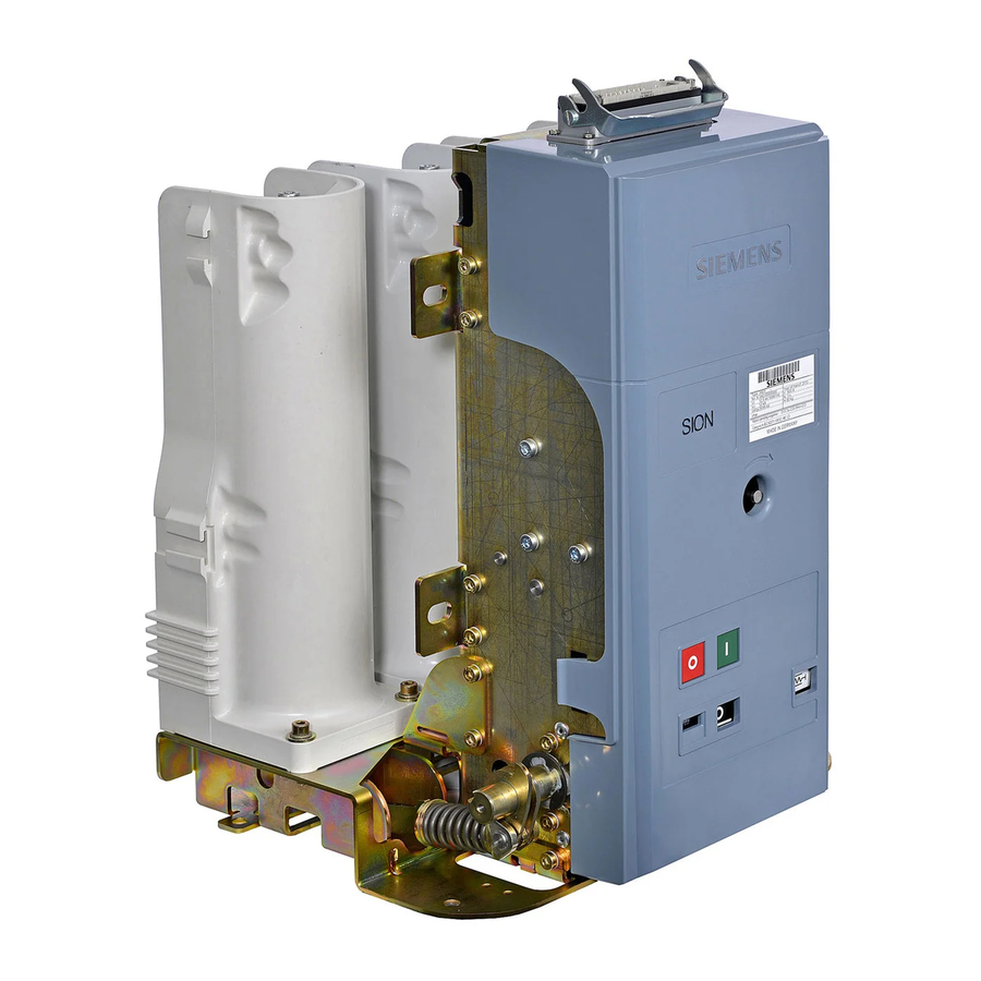
Page 13: Description
Description Description Design The images shown are examples; not all the variants of the vacuum circuit-breaker are shown here. Fig. 8 12 kV, operating side with separating shells Fig. 9 12 kV, pole side (towards system side) Fig. 10 24 kV, operating side with separating shells Fig. - Page 14 Description Fig. 12 Operating mechanism side with separating Fig. 13 Pole side shells (towards operating mechanism side) Fig. 14 Operating mechanism side with separating shells (towards operating mechanism side) and withdrawable part Withdrawable part Pole head 20.1 Cover Vacuum interrupter Rating plate Pole contact plate Low-voltage plug connector (-X0),...
- Page 15 Description Operating mechanism The operating mechanism contains all the electrical and mechanical components re- quired to close or open the vacuum circuit-breaker. Isolators transfer the switching movement to the pole assemblies. The operating mechanism is covered by a removable cover (20.1). Operating and indicator elements Fig.
- Page 16 Description Secondary equipment Auxiliary switch (-S1) 54.3 Position switch (-S3), control for (-K1) Low-voltage plug connector (-X0), (optional) 54.4 Position switch (-S4), message “Closing spring charged” 33.1 Connector strip (-X1.2 and -X1.4), 20-pole 54.6 Position switch (-S6), circuit-breaker tripping signal 33.2 Plugs (-X01) and (-X02) for withdrawable part (optional) (optional, not shown)
- Page 17 Description Auxiliary switch (-S1) 54.5 Position switch (-S5), electrical closing lock-out or key- Low-voltage plug connector (-X0), (optional) operated interlock (optional) 33.1 Connector strip (-X1.2 and -X1.4), 20-pole 54.6 Position switch (-S6), circuit-breaker tripping signal 33.2 Plugs (-X01) and (-X02) for withdrawable part (optional) (optional, not shown) 33.3 Plug (-X1) only when ordering the 20-pole connector strip...
- Page 18 Description Equipment ® Basic equipment The basic equipment of the vacuum circuit-breaker SION contains the following: Motor 3AY1411, for charging the closing spring (-M1) Position switch 3AX4206-0A, for motor control (-S21) Anti-pumping device • electrical 3AY1420 (-K1) • mechanical Position switch 3AX4206-0A, control of the anti-pumping device...
- Page 19 Description Motor (-M1) After the supply voltage is applied and if the closing spring is discharged, the motor starts immediately and is automatically deactivated internally after charging has taken place. For power consumption see table Fig. 20. In the short charging time, the motor operates in the overload range.
- Page 20 Description Auxiliary contactor (-K1) If simultaneous electrical CLOSE and OPEN commands are continuously applied to the vacuum circuit-breaker, it returns to the open position after being closed. The function of the auxiliary contactor (-K1) causes the vacuum circuit-breaker to pause at this point until the CLOSE command is given again.
- Page 21 Description First shunt release (-Y1) In the case of the first shunt release (-Y1), the electrical- ly fed tripping pulse is passed to the "OPEN" latch by means of a directly acting magnet armature, thus open- ing the vacuum circuit-breaker. The first shunt release (-Y1) is not designed for continu- ous operation and is terminated within the circuit-breaker via the auxiliary switch (-S1) at the factory.
- Page 22 Description Auxiliary switch (-S1) Auxiliary switch (-S1) is available for delivery in two ver- sions: With 6 normally open contacts or 12 normally closed contacts each. Contacts available on the custom- er's premises - see circuit diagram supplied. Fig. 26 Auxiliary switch (31) Power consumption Rated insulation voltage:...
- Page 23 Description Circuit-breaker tripping signal (-S6) 3AX4206-0A The position switch (-S6) makes contact briefly when the vacuum circuit-breaker is opened by means of an elec- trical release. This contact can be used for a signal. Fig. 27 Circuit-breaker tripping signal (54.6) A further shunt release, current transformer-operated release or undervoltage re- lease can be installed as a second or third release.
- Page 24 Description C.t.-operated release (-Y4), (-Y5) 3AX1102, (-Y6) 3AX1104 Fig. 30 C.t.-operated release (51.3) Fig. 31 C.t.-operated release (51.3) The c.t.-operated releases (-Y4), (-Y5) or (-Y6) consist of an energy store, an un- latching fixture and an electromagnetic system. If the tripping current is exceeded (90 % of the transformer-operated release's rated current), the stored energy mech- anism is unlatched, thus initiating opening of the vacuum circuit-breaker.
- Page 25 Description Undervoltage release (-Y7) 3AX1103 Note The undervoltage release (-Y7) may only be operated with the supplied series re- sistor (-R1). Note For circuits (mechanical or electrical), the undervoltage release 3AX1103… must be connected to control voltage, as otherwise a switch-on is not possible (see “Removing the transport block from the undervoltage release”, page 48).
- Page 26 Description Heater (-R01) for condensation water protection (optional) The heater limits condensation and corrosion of the vac- uum circuit-breaker. To this end, the heater has to be connected to the supply voltage (see circuit diagram included with the delivery). Fig. 34 Example - heating (59.4) WARNING Risk of burns!
-
Page 27: Interlocks
Description WARNING Risk of crushing! Mechanical parts can move quickly, even if they are remote-controlled. Contact with mechanical parts or parts under spring charge can lead to crushing of body parts. • Do not reach into openings. • Do not touch pole assemblies or circuit-breaker shaft. •... - Page 28 Description 35 ±0.3 mm Fig. 35 Mechanical interlock Stroke in the OPEN switch position (min. 5 mm, max. 10 mm) Sensing or actuation component (cross-section max. 14 mm x 3 mm, actuation force min. 50 N, max. 450 N) c + d See dimension drawing CLOSED switch position spacing Sectional view...
- Page 29 Description Key-operated interlock 3AX1437 (optional) If the vacuum circuit-breaker is equipped with a key-op- erated interlock, it is possible to mechanically prevent both manual closing and electrical closing (position switch -S5). To lock the vacuum circuit-breaker, press and hold the OPEN pushbutton until the key is turned to the CLOSED position (vertical).
-
Page 30: Rating Plate
Dimensions and weights The dimensions of the vacuum circuit-breaker can be taken from the relevant dimen- sion drawing. If needed, they can be obtained from your Siemens representative. The weight is indicated on the vacuum circuit-breaker rating plate (see Fig. 38) or refer to the associated dimensional drawing. -
Page 31: Ambient Conditions
Description Ambient conditions Occasional condensation may occur under these ambi- ent conditions. ® Vacuum circuit-breakers SION are suitable for use in the following climate classes according to IEC 60721, part 3-3: Class • Climatic ambient conditions: • Biological ambient conditions: •... -
Page 32: Operating Times
Description Operating times Closing time < 60 ms Opening time First shunt release (-Y1) < 45 ms Second/third release (-Y2, -Y3, -Y4, -Y5, -Y6, -Y7) < 45 ms Arcing time < 15 ms Break time First shunt release (-Y1) < 75 ms Second/third release (-Y2, -Y3, -Y4, -Y5, -Y6, -Y7) <... -
Page 33: Circuit Diagrams
Description Circuit diagrams The circuit diagrams show deliverable components with their wiring options. The circuit diagrams for the vacuum circuit-breaker are compiled depending on your order. Mechanical manual closing and electrical closing Extended auxiliary switch “OPEN” release -Y4, -Y5 Fig. 43 Sample circuit diagram 64-pole plug connector (part 1) of the vacuum cir- cuit-breaker Electrical closing lock-out (optional, only) - Page 34 Description The unassigned auxiliary switch terminals are wired up with the 64-pole plug bottom as shown. Normal auxiliary switch Extended auxiliary switch 9862-75 No wiring required if Second shunt release (-Y2) available Undervoltage release (-Y7) available Fig. 44 Example - auxiliary switch terminals System wiring Tripping via Tripping via NO con-...
-
Page 35: Mounting
Mounting Mounting DANGER High-voltage - danger to life Touching live parts causes an electric shock. • Do not touch live parts! • When work is performed on the switchgear, the switchgear must be de-ener- gized and earthed! • The work described in the following sections must only be performed when the switchgear has been de-energised: Take safety measures to prevent it from being switched back on! Observe industrial safety regulations! -
Page 36: Fixing In The Switching Cubicle
Any warranty claims are lost in the event of such incorrect operation. ® Use suitable means to prevent the vacuum circuit-breaker SION from closing if the cover has been removed and the mechanical interlock has been actuated. - Page 37 Mounting Removing and mounting the covers Remove the covers to mount the fixing lugs. Removing and mounting the cover Fig. 47 Removing the cover Fig. 48 Mounting the cover Removing • Pull off both the engaging hooks of the cover (20.1) simultaneously. •...
- Page 38 Mounting Removing and mounting the cover 4 ±0.4 Nm Fig. 49 Removing the cover Fig. 50 Mounting the cover Removing • Loosen both upper M6 hexagonal bolts but do not unscrew them. • Unscrew the bottom four M6 hexagonal bolts with the contact washers. •...
- Page 39 Mounting Mounting the PG fitting The version with a connector strip (without low-voltage plug) is supplied with a PG fitting and fasteners (in the accessories pack). The PG fitting serves to bundle and protect the cables coming from the low-voltage interface. Note Self-tapping screws are suitable for single use only.
- Page 40 Mounting Mounting the system-side separating shells System-side separating shells (47) can be used to insulate the individual poles from each other if there is restricted terminal space. When using system-side separating shells (47), you can use main conductors with a max. diameter or cross-section of 60 mm. Fig.
- Page 41 Mounting Fig. 56 Mounting separating shells Fig. 57 Engaging separating shells • Place separating shell (47) onto the rib (arrow a) from the top at a slight angle. • Push the bottom part of the separating shell (47) against the pole shell (46) until it engages audibly.
- Page 42 Mounting threads only). Fixing to the withdrawable For fixing to the withdrawable part, remove the cover prior to mounting (see “Remov- part ing and mounting the covers”, page 37) and fix the cable harness in the operating mechanism (see “Connecting the low voltage”, page 46). Fig.
- Page 43 Mounting Mounting the IP plate (optional) The IP plate (internal arc protection plate) is a protective plate that separates the high-voltage area from the drive area and provides additional protection in the event of a fault arc. Note The IP plates are classed as accessories. Whether mounting is possible depends on the version of the switching device.
- Page 44 Mounting Mounting the shaft covers Note The shaft covers are classed as accessories. Whether mounting is possible depends on the version of the switching device. You can ask the manufacturer if mounting is possible. A mounted shaft cover prevents access to open moving parts and prevents inju- ries.
-
Page 45: Earthing
Mounting Earthing Note ® If the vacuum circuit-breaker SION is installed into an earthed metal framework and is connected permanently and electrically conductive, no separate earthing is required. Place serrated washers under the screw heads when fixing the vacuum circuit- breaker in this case. -
Page 46: Connecting The Low Voltage
Mounting Connecting the low voltage Connect the low-voltage connecting cables in the customer's switchgear in such a way that safe operation as per the supplied circuit diagram is guaranteed. Low-voltage interface (-X0), 64-pole 3AX1134 For connection of the control line, the standard version of the vacuum circuit-breakers is equipped with a 64-pole low-voltage interface (-X0). - Page 47 Mounting Connecting the control lines for 20-pole connector strip CLOSED signal potential (-Y9; 24 V to 240 V) (customer Faston crimp recepta- -Y2/-Y4/-Y6/-Y7* cle with insulating sleeve in the accessory -Y7* pack) -X1.3, -X1.4 Each as 10-pole plug (customer plug for -S6* -X1.3 and -X1.4 in the accessory pack) Internally wired...
- Page 48 Mounting Fig. 74 Mounting the plug for the withdrawable part Fig. 75 Mounting the plug for the withdrawable part Mounting the plug • Insert the plug bottom (-Q0) into the frame as far as it will go and let it engage. •...
-
Page 49: Electrical Connection Of The Main Conductors
• Impact depths for spring pins or spiral spring pins can be found in table “Screw-in depths”, Fig. 79. The conductor bars can be purchased from the Siemens Service Center. Preparing contact surfaces Note Clean silver spray-plated and copper spray-plated contact areas with a cloth; do not brush. - Page 50 Mounting Carefully brush the connecting surfaces of the conductor bar cross-wise with a steel brush until they are bright, and wipe off any residue using a clean cloth. After cleaning, very lightly grease the bright contact surfaces with acid-free Vaseline (e.
- Page 51 Mounting able screwdriver or socket spanner. Tightening torque for M12: 40 ±4 Nm M16: 100 ±10 Nm Tightening torques apply to greased threads only. Securing with a spiral The conductor bars can be secured against twisting with a spiral spring pin accord- spring pin ing to ISO 8748 or a spring pin according to ISO 8752 —...
- Page 52 Mounting Fig. 84 Fitting the contact arms (22) Fig. 85 For contact arms with Ø 40 mm, inserting the contact arm adapter (22.2) on the rear • Fit the contact arms. • Mount separating shells (if present, see “Mounting the system-side separating shells”...
- Page 53 Mounting adapter) on one side of the inside (round outer edge) on the contact fingers with Molykote Longterm 2. • Fit contact system onto threaded rod and contact arm, observing position of the contact system (round outer edge towards contact arm). •...
-
Page 54: Inserting The Vacuum Circuit-Breaker Sion ® With Withdrawable Part
Mounting ® Inserting the vacuum circuit-breaker SION with withdrawable part Fig. 89 Example - inserting into guide rails Fig. 90 Example - inserting and locking • Fit the vacuum circuit-breaker with withdrawable part into system-side guide rails. • Push the vacuum circuit-breaker with withdrawable part into the guide rails until they hit the side stops (large arrow), moving locking handles towards the middle of the withdrawable part (small arrows). - Page 55 Mounting Fig. 91 Example - moving in guide rails • Insert the handle of withdrawable part 3AX1430-2C into the coupling of the with- drawable part. • Turn inserted withdrawable part handle 3AX1430-2C clockwise in order to move the vacuum circuit-breaker to a perceivable end stop. Travel path lengths (optional): 180, 200 and 220 mm for all vacuum circuit-breakers up to 17.5 kV and 260 mm for all vacuum circuit-breakers with 24 kV.
- Page 56 Mounting Blank page 9229 0025 176 0- 2018-01-18...
-
Page 57: Operation
Operation Operation DANGER High voltage - danger to life! Touching live parts causes an electric shock. • Do not touch live parts! • Ensure that the vacuum circuit-breaker is operated only by qualified person- nel who are familiar with the operating instructions and who observe the warning notices. -
Page 58: First Closing Operation
Do not commission the vacuum circuit-breaker if there are malfunctions. If the malfunctions or the damage cannot be remedied, contact a sales represent- ative or Siemens Service and, if necessary, send back the vacuum circuit-break- Position indicator and spring state indicator when charging the closing... - Page 59 Operation Charging the closing spring WARNING Risk of injury if hand cranks other than the original hand crank are used. When the supply voltage is present, the motor immediately recharges the spring after a closing operation. If the hand crank does not have a slip coupling, the hand crank will also rotate.
-
Page 60: Closing
Operation Closing Provided there is no lock-out due to a mechanical interlock, send the closing com- mand via the CLOSE pushbutton or the corresponding command element until the vacuum circuit-breaker is closed and shows and signals the CLOSED switch posi- tion. -
Page 61: Maintenance
The highest permissible mechanical operating cycle number • 10 000 maintenance-free • 30 000 with maintenance by personnel authorised by Siemens. Preliminary work • Prior to starting work on the vacuum circuit-breaker, observe the local safety regulations for high-voltage devices and the "5 safety rules" as per EN 50110-1. -
Page 62: Service Life Of The Vacuum Interrupters
Accessories and spare parts Replacing spare parts To ensure that the device operates reliably, spare parts are permitted to be replaced only by personnel trained and certified by Siemens. CAUTION Risk of injury! The vacuum circuit-breaker should be taken out of the switchgear or switch cab- inet for servicing. -
Page 63: Manufacturer's Product Liability
If the packaging is no longer needed, it can be fully recycled. Hazardous substances When delivered by Siemens, the product does not contain any hazardous substanc- es within the scope of the Hazardous Substances Ordnance applicable to the terri- tory of the Federal Republic of Germany. For operation outside the Federal Republic of Germany, the applicable local laws and regulations must be complied with. - Page 64 Maintenance Blank page 9229 0025 176 0- 2018-01-18...
-
Page 65: Index
Index Index High-voltage protective earthing ......45 Accessories available for order ......62 Altitude correction factor ........31 Installation altitudes ..........31 Ambient conditions ..........31 Installation position ..........36 Anti-pumping device ..........18 Interlock, mechanical ........18 Areas of application ..........11 Interlocks ............... - Page 66 Index Rated frequency ............ 30 Rated lightning impulse withstand voltage .... 30 Rated normal current ........30 Rated operating sequence ........30 Rated power frequency withstand voltage .... 30 Rated short-circuit breaking current ....30 Rated voltage ..........30 – Rating plate ...........
-
Page 67: Central Legend
Central legend Central legend Withdrawable part 57.1 Opening for hand crank Operating mechanism 57.2 Hand crank coupling 20.1 Cover Operations counter Rating plate 59.2 Mechanical interlock or sensing (optional) Contact arm 59.3 Key-operated interlock (optional) 22.1 Threaded bolt 59.4 Heater (-R01), for condensation water pro- tection (optional) 22.2 Contact arm adapter... - Page 68 Published by Siemens AG Energy Management Division Medium Voltages & Systems Schaltwerk Berlin Nonnendammallee 104 13629 Berlin Germany...
Need help?
Do you have a question about the SION and is the answer not in the manual?
Questions and answers