Advertisement
Quick Links
Advertisement

Subscribe to Our Youtube Channel
Related Manuals for Danatronics ECHO 7 Series


Summary of Contents for Danatronics ECHO 7 Series
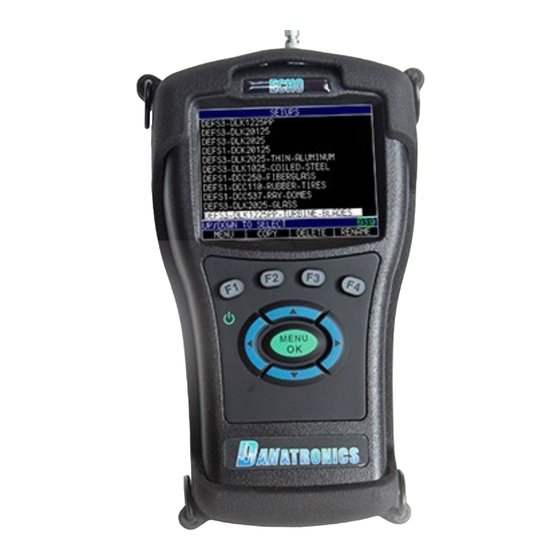
- Page 1 Quick Start Guide ECHO 7 Thickness Gages V 2.0...
- Page 2 Batteries ECHO Series Thickness Gages come standard with a rechargeable Li-Ion battery located on the back of the gage under the door with the screw. Fully charge your unit before using by plugging the USB cable into the top of the gage and to the included AC wall adapter. When charging, the F4 key will light up blue.
- Page 3 2. Using Keypad Functions Function keys, or F keys, (e.g., F1, F2, F3, F4) have various gage functions and may change depending on the display screen. View the bottom of the display screen for the function that corresponds with the appropriate F key. For example, F1 may correspond with the Save function, F2 with the Freeze function, or F4 can change the display format of how large the thickness value is.
- Page 4 couplant or cable attenuation. C3 is also ideal for thin materials as well as materials such as steel, aluminum and ceramics where multiple echoes exists. Class 5 or the A2-DFR CLF4 transducer setup found in the transducer menu of the ECHO 7/Precision meets Boeing’s specification to inspect a range from .007”- 1.0”...
- Page 5 Class 2 with interface echo at left and first detected backecho on right. Also shown in interface blank (dead zone) below the interface echo. Class 3, marker shows measured time between echo 1 and echo 2 after an interface echo. Also shown is the blank after first A2-DFR CLF4 transducer Class Five for...
- Page 6 Make any necessary adjustments then F4 for to go to the Measurement screen Saving and discarding an altered stored setup: When making a change to any parameter to a default setup, the ECHO will put an asterisk next to the file indicating something has changed. Your choice is to Save the new setup by pressing F2 and typing in a new name or discarding the changes by pressing F3.
-
Page 7: Taking Measurements
Velocity Calibration Only To perform a velocity calibration, press the Menu/OK key and scroll to calibration and press Menu/OK To perform a velocity calibration, While measuring the thickest piece of your test sample, select F3 - VEL key. After pressing the F3 key, you can take the transducer off the test block. If the displayed measurement is different than the known value of the step, use the up or down arrow key to adjust the displayed value to the known value of the step. -
Page 8: Changing Resolution
After an Auto Zero is performed on a selected transducer, the unit automatically goes to the Measure mode as shown below. To take thickness readings, simply apply couplant (fluid in gage kit bottle) to the material’s surface followed by the transducer to measure the thickness. Depending on the settings, the display may show other parameters. - Page 9 7. Changing the Parameter Settings To change any parameter settings, press the F1 – Menu key from the Transducer selection screen. Use the up and down arrow keys to select the Display, Initial Settings, or Measurements option depending on the setting you wish to change and press the MENU/OK key. Use the arrow keys to select any of the settings you wish to change.
Need help?
Do you have a question about the ECHO 7 Series and is the answer not in the manual?
Questions and answers