
Related Manuals for Gardner Denver APEX15-18A


Summary of Contents for Gardner Denver APEX15-18A
- Page 1 13-25-607 Version: 00 July 30, 2014 APEX SINGLE STAGE BASE- MOUNTED and TANK MOUNTED COMPRESSORS AirSmartä G2 Controller MODELS-APEX15-18A 15 and 18 kW 60HZ OPERATING AND SERVICE MANUAL...
-
Page 3: Support Services
A full line of factory tested AEON™ compressor lubricants specifically formulated for use in Gardner Denver compressors. -
Page 4: Warning - Prohibition - Mandatory Label Information
WARNING – PROHIBITION – MANDATORY LABEL INFORMATION Gardner Denver Rotary Screw compressors are the result of advanced engineering and skilled manufacturing. To be assured of receiving maximum service from this machine, the owner must exercise care in its operation and maintenance. This book is written to give the operator and maintenance department essential information for day-to-day operation, maintenance and adjustment. - Page 5 Indicates a hazard with a medium level of risk which, if not avoided, COULD result in death or serious injury. Asphyxiation Hazard – Poisonous Fumes or Toxic Gases in Compressed Air Indicates a hazard with a low level of risk which, if not avoided, MAY result in a minor or moderate injury.
-
Page 6: Safety Precautions
SAFETY PRECAUTIONS Safety is everybody’s business and is based on your use of good common sense. All situations or circumstances cannot always be predicted and covered by established rules. Therefore, use your past experience, watch out for safety hazards and be cautious. Some general safety precautions are given below: Failure to observe these notices will result in injury to or death of personnel. -
Page 7: Table Of Contents
TABLE OF CONTENTS Maintain Compressor Reliability And Performance With Genuine Gardner Denver Compressor Parts And Support Services ............................. 1 Instructions For Ordering Repair Parts ..................... 1 Warning – Prohibition – Mandatory Label Information ................2 Safety Precautions ..........................4 Index ............................... 6 Section 1, General Information ........................ -
Page 8: Index
INDEX Air Cooled Unit ..........12 Motor Lubrication ........... 17 Air Filters Oil Reservoir Section 7.............47 Drain ............13 Air Flow In Compressor System ....... 8 Piping Air Receiver Control ............15 Auxiliary ............15 Prestart-Up Instructions........18 Belt Drive System Air Filter ............18 Section 8.............50 Compressor Oil .......... - Page 9 LIST OF ILLUSTRATIONS Figure 1-1 - Compressor Cycle ........................ 8 Figure 1-2 – Compressor Illustration - External Details ................9 Figure 1-3 – Compressor Illustration - Internal Details ................10 Figure 2-1 – Typical Compressor Room ....................13 Figure 2-2 – Air Flow Chart ........................13 Figure 2-3 –...
-
Page 10: Section 1, General Information
SECTION 1 GENERAL INFORMATION Figure 1-1 - COMPRESSOR CYCLE COMPRESSOR - The rotary screw compressor is a single stage, positive displacement rotary machine using meshing helical rotors to effect compression. Both rotors are supported between high capacity anti- friction bearings located outside the compression chamber. Roller bearings are used at the inlet end of the rotors to carry part of the radial loads. -
Page 11: Figure 1-2 - Compressor Illustration - External Details
300UCC804-C (Ref. Drawing) Page 1 of 1 Figure 1-2 – COMPRESSOR ILLUSTRATION - EXTERNAL DETAILS... -
Page 12: Figure 1-3 - Compressor Illustration - Internal Details
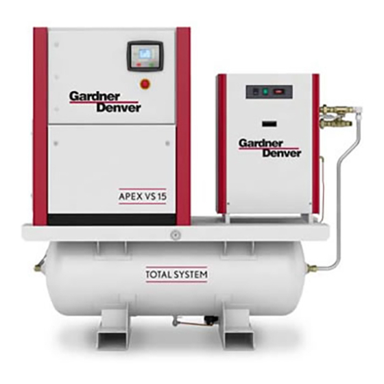
300UCC797-B (Ref. Drawing) Figure 1-3 – COMPRESSOR ILLUSTRATION - INTERNAL DETAILS Page 2 of 2... - Page 13 307UCC804-B (Ref. Drawing) Page 1 of 1 Figure 1-4 – COMPRESSOR ILLUSTRATION – TOTAL SYSTEM...
-
Page 14: Section 2, Installation
SECTION 2 INSTALLATION GENERAL - On receipt of the unit, check for any damage that may have been incurred during transit. Report any damage or missing parts as soon as possible. Do not electric weld on the compressor or base; bearings can be damaged by passing of current. -
Page 15: Figure 2-1 - Typical Compressor Room
For continuous efficiency, the cooler cores must be periodically cleaned with either vacuum or compressed air. If wet cleaning is required, shield motor and spray on a mild soap solution and flush with clean water. NOTICE Coolers are aluminum; do not use any cleaning solution that is not compatible with aluminum. -
Page 16: Figure 2-3 - Cold Weather Installation
ENCLOSURE - The compressor, electric motor, oil cooler and aftercooler are mounted inside the enclosure. Service panels are provided for maintenance access. Be sure to allow enough space around the unit for the panels to be removed. Any of the enclosure panels may be removed by opening the latch and lifting it up slightly. - Page 17 ᴼ F, 0 ᴼ C), contact Gardner Denver for recommendations. When Using a Total System with a compressed air dryer option, refer to Section 10 details. Remember unsheltered (outside) installations should be avoided where possible. Installation next to a heated building where enough heat can be used to keep the compressor room above freezing will save many complications in the operation and installation of the unit.
- Page 18 Discharge air used for breathing will cause severe injury or death. Consult filtration specialists for additional filtration and treatment equipment to meet health and safety standards. ELECTRICAL WIRING - Standard Units - The compressor package is factory wired for all connections from the starter to the motor, for the horsepower and voltage specified on the order.
- Page 19 Line Reactor - A line reactor provides conditioning of the electrical power supply to the compressor package by attenuating noise and fluctuations. Is shall be required in your particular application if any of the following conditions exist: · Transformer KVA is greater that recommended - see Figure 2 - 5 ·...
-
Page 20: Section 3, Starting & Operating Procedures
For instructions on checking the oil and the proper oil level, refer to “Oil level gauge”, SECTION 5 see page 36 Do not mix different type oils. Standard Unit is shipped filled with Gardner Denver AEON 4000 lubricant which is suitable for the first 4000 hours under normal operating conditions. Other AEON lubricants are available. - Page 21 Failure to properly ground the compressor package could result in controller malfunction. V-Belt System - Refer to Section 8 page 50 for detailed instruction to unpack and check the alignment of the belt system. The motor jacking hardware must be re-configured, the disposable spacer removed, and belts engaged and the belt sheaves alignment checked prior to compressor operation.
- Page 22 11. Target Pressure - This is the package discharge pressure that the controller maintains by modulating the motor speed with the variable frequency drive. See "Operational Settings" menu in Controller Operating and Service Manual. Operation at excessive discharge air pressure can cause personal injury or damage to equipment.
- Page 23 The controller has an automatic start/stop sequence built in. You do NOT need to close the air service valve. Closing the air service valve on start-up or prior to shutdown will cause rapid cycling, and could cause a high pressure shutdown.
- Page 24 Quick Start Guide For your convenience, the following excerpt from the Controller Operating and Service Manual is presented to assist in programming the basic operating parameters. However, we strongly recommend you read the Controller Operating and Service manual before attempting operating the compressor package.
-
Page 25: Section 4, Controls & Instrumentation
CONTROLS & INSTRUMENTATION GENERAL DESCRIPTION The Gardner Denver rotary screw compressor is pre-wired with all controls, motor, and starter for the voltage and horsepower at the time of ordering. It is necessary only to connect the compressor unit to the correct power supply and to the shop air line. - Page 26 Power Supply – This single-phase device supplies all 24 VDC needs within the control enclosure from the available AC supply line. Terminal Strip - This device provides an interconnection between the ASG2 controller and the low voltage hardware such as sensors and switches within the enclosure. Variable Frequency Drive - The main motor coupled to the compressor is energized by a pulse-width modulated, variable frequency drive (aka a VFD).
-
Page 27: Figure 4-4 - Wiring Diagram - Wye-Delta (200-230/460 Volt)
306UCC546-A (Ref. Drawing) Page 1 of 4 Figure 4 - 2 – WIRING DIAGRAM – VS (200-460 VOLT) - Page 28 306UCC546-A (Ref. Drawing) Page 2 of 4 Figure 4 - 3 – WIRING DIAGRAM – VS (200-460 VOLT)
-
Page 29: Figure 4-4 - Wiring Diagram - Wye-Delta (200-230/460 Volt)
306UCC546-A (Ref. Drawing) Page 3 of 4 Figure 4 - 4 – WIRING DIAGRAM – VS (200-460 VOLT) -
Page 30: Figure 4-4 - Wiring Diagram - Wye-Delta (200-230/460 Volt)
306UCC546-A (Ref. Drawing) Page 4 of 4 Figure 4 - 5 – WIRING DIAGRAM – VS (200-460 VOLT) -
Page 31: Figure 4-5 - Wiring Diagram - Wye-Delta (575 Volt)
307UCC546-A (Ref. Drawing) Page 1 of 4 Figure 4 - 6 – WIRING DIAGRAM – VS (575 VOLT) -
Page 32: Figure 4-5 - Wiring Diagram - Wye-Delta (575 Volt)
307UCC546-A (Ref. Drawing) Page 2 of 4 Figure 4 - 7 – WIRING DIAGRAM – VS (575 VOLT) -
Page 33: Figure 4-5 - Wiring Diagram - Wye-Delta (575 Volt)
307UCC546-A (Ref. Drawing) Page 3 of 4 Figure 4 - 8– WIRING DIAGRAM – VS (575 VOLT) -
Page 34: Figure 4-5 - Wiring Diagram - Wye-Delta (575 Volt)
307UCC546-A (Ref. Drawing) Page 4 of 4 Figure 4 - 9 – WIRING DIAGRAM – VS (575 VOLT) - Page 35 MISCELLANEOUS CONTROL DEVICES - Refer to Figure 4 - 10, page 35 for the schematic diagram of the control system. Intake [Air] Filter (1) - Captures solid impurities in the air stream entering compressor inlet. It also attenuates noise emitted by the compressor inlet. Inlet-Valve Assembly (2) - This device controls the intake of atmospheric air entering the compressor during the Load/Unload phases of operation.
- Page 36 3/2 Solenoid Valve (Y) - This valve controls the position of the inlet valve in response to signals from the AirSmart Controller. It also provides a small amount of scavenge air to carry off compressor shaft seal oil challenge. See inlet valve assembly (2) for more information. Pressure Sensor - Sump Dry Side (B1) - This device is connected after the minimum pressure valve.
-
Page 37: Figure 4 6 - Piping And Instrumentation Illustration
301UCC797-F (Ref. Drawing) Figure 4 - 10 – PIPING AND INSTRUMENTATION ILLUSTRATION... -
Page 38: Section 5, Lubrication. Oil Cooler, Oil Filter & Separator
AEON lubricants are available through your authorized Gardner Denver compressor distributor. OIL SPECIFICATIONS - The standard factory fill compressor lubricant is Gardner Denver AEON 4000, a superior semi-synthetic blend of petroleum stock and various protective additives, suitable for year-round operation. - Page 39 Before draining, adding, or changing the lubricant oil in the compressor, be aware of the following hazards associated with these tasks: Air/oil under pressure will cause severe personal injury or death. Shut down compressor, relieve system of all pressure, disconnect, tag and lockout power supply to the starter before removing valves, caps, plugs, fittings, bolts and filters.
- Page 40 All materials used in Gardner Denver compressor units are compatible with AEON 9000SP Lubricant. Use caution when selecting downstream components such as air line lubricating bowls, gaskets and valve trim. AEON 9000SP Synthetic Lubricant is not compatible with low nitrile Buna N or acrylic paints.
- Page 41 ADDITION OF OIL BETWEEN CHANGES must be made when the oil level is below the minimum level of the sight glass as read while the unit is completely off and blown down, and the foam has settled out. Be sure the unit is completely off and that no air pressure is in the oil reservoir. Disconnect, tag and lockout the power supply to the starter.
-
Page 42: Figure 5-2 - Dew Point Chart °F
Pressure Dew Point Trend (100% r.h.) 100psig 125psig 150psig 175psig Am bient Tem p - oF Figure 5 - 2 – Dew Point Chart °F Pressure Dew Point Trend (100% r.h.) 6.9bar 8.6bar 10.3bar 12.1bar 10.0 15.0 20.0 25.0 30.0 35.0 40.0 45.0... -
Page 43: Figure 5-4 - Oil Change Interval
Operating conditions and the appearance of the drained oil must be surveyed and the oil change intervals planned accordingly by the user. Gardner Denver offers a free oil analysis program with the AEON lubricants, and we recommend a sample be sent in at 100 hours on a new unit. - Page 44 7. Install the oil filler plug and operate the unit for about a minute allowing oil to fill all areas of the system. Check for leaks. 8. Shut down unit, allowing the oil to settle, and be certain all pressure is relieved. 9.
- Page 45 AIR / OIL SEPARATOR - This device provides the final (2%) of the air/oil separation - typically 2ppm oil content at the final discharge of the compressor package. It is housed in a removable spin-on cartridge. Its high level of performance may be affected by the following conditions: ·...
-
Page 46: Section 6, Heat Exchangers (Oil/Air)
HEAT EXCHANGER MAINTENANCE - All the required hardware, mechanical and electrical connections have been made at the Gardner Denver factory, thus the only regular maintenance required is to keep the exterior core fins free from dirt and other airborne debris per the following procedure:... - Page 47 Compressor, air/oil sump and all piping and tubing may be at high temperature during and after operation. Do not attempt inspection or cleaning of air-cooled heat exchangers until cooling fan has stopped rotating. Disconnect lockout and tag out package from power supply.
-
Page 48: Figure 6-2 - Cooler Access
The ventilation system for the air-cooled package relies on positive back pressure to cool the heat exchanger. Make sure that the enclosure panels that surround the heat exchanger area are closed during compressor operation, or the compressor discharge temperature will reach shutdown levels quickly. -
Page 49: Section 7, Air Filters
In turn, the longevity of the filter element depends on the cleanliness of the local environment. NOTICE Use only genuine Gardner Denver air filter elements on Gardner Denver compressor units. Genuine parts are available through your authorized Gardner Denver distributor. -
Page 50: Figure 7-1 - Compressor Air Filter
PACKAGE PRE-FILTER MAINTENANCE 1. Remove all four (4) wing-nuts securing the pre-filter cover to the grill assembly and remove the pre-filter media. See Figure 7- 2 for component details. Note: do not remove the fan grill. 2. Cleanse the pre-filter media with compressed air or with water to remove debris trapped in its fibers. - Page 51 VFD VENTILATION FILTER INSPECTION / REPLACEMENT 1. Locate the VFD filter access cover on the bottom, right hand side of the electrical enclosure, as viewed from the rear with the bi-fold panels open. 2. Loosen the two (2) slotted screws holding the cover in place. Slide the cover upwards to uncover the air filter edge.
-
Page 52: Section 8, Belt Drive System
SECTION 8 BELT DRIVE SYSTEM The motor power is transmitted to the compressor with a system comprised of heavy-duty v-belts, sheaves, and bushings. Belt tension is provided by the motor weight with the help of a free-pivoting bracket -see Fig 1-2, Page 11, for details. Figure 8- 1 –... -
Page 53: Figure 8-3 - Measuring Angular Misalignment
The motor jacking hardware must be re-configured, the disposable spacer removed, and belts engaged and the belt sheaves alignment checked prior to compressor operation. Failure to do so will prevent compressor operation and/or component damage. 1. Unlatch and remove the door panel opposite to the main cooling fan panel to gain access to the v-belt system –... - Page 54 (after loosening the jam nut) and raising the motor body until the v-belts can be dismounted from the motor sheave. Replace the old belts with new ones. For proper belt life, use only genuine Gardner Denver belts. Check the sheave alignment.
-
Page 55: Section 9, Servicing Of Miscellaneous Devices
SECTION 9 SERVICING OF MISCELLANEOUS DEVICES This section will cover basic maintenance of various control devices used with the compressor module. Refer to Fig 9-1, Page 53, for pictorials of referenced hardware. INLET CONTROL VALVE ASSEMBLY Inlet-Valve Assembly (2) - This device is located within and below the intake flange of the compressor - see Figure 9- 1 for internal details and Figure 4-6, page 29 for schematic details. -
Page 56: Figure 9-2 - Inlet Valve Body Hex
Inlet Valve (Body) Inspection - The valve does not require maintenance or lubrication. If air/oil leaks develop across the valve disc during pressurized conditions (e.g., machine stopped), valve seals should be inspected for wear and tear signs: 1. Be sure the unit is completely off and oil sump is depressurized. 2. -
Page 57: Figure 9-3 - Pressure Relief Valve
PRESSURE RELIEF VALVE Pressure Relief Valve - This device protects the pressure-containing components of the compressor package against pressures exceeding 218 psig. It is installed on the wet-side of the oil sump. Figure 9- 3 - Pressure Relief Valve Before inspecting the pressure relief valve, release air pressure, lockout and tagout the power supply to the compressor package. -
Page 58: Figure 9-4 - Minimum Pressure Valve And Seat
MINIMUM PRESSURE VALVE Minimum Pressure Valve Inspection – This device has no user-serviceable or repairable components. If it fails to maintain adequate minimum pressure (70psig) or fails to check the backflow of system compressed air after compressor stoppage, replace it as follows: Figure 9- 4 - Minimum Pressure Valve and Seat Air/oil pressure will cause severe personal injury or death. -
Page 59: Figure 9-5 - Thermal Mixing Valve
Input Shaft Seal Maintenance – This device has no user-serviceable or repairable components. If oil leaks past its seal and unto the external portion of the shaft, contact Gardner Denver to have it inspected and/or repaired by a trained mechanic. -
Page 60: Figure 9-6 - Compressor Module Hardware
308UCC810-C (Ref. Drawing) Page 1 of 1 Figure 9- 6 – Compressor Module Hardware... -
Page 61: Section 10, Tank Mounted Compressor - Total System
SECTION 10 TANK MOUNTED COMPRESSOR - TOTAL SYSTEM DESCRIPTION - The basic compressor can be furnished mounted on an optional compressed air received (120 and 240 gallon sizes) and paired to an optional RNC [refrigerated non-cycling] compressed air dryer, as shown on Figure 10- 1. ·... - Page 62 · Installation - Package must installed in a location with an ambient temperature range of 40ºF to 110ºF (3ºC to 43ºC). Consult Gardner Denver for operation outside this range. · Discharge service pipe - The discharge service line connection is provided at the outlet of the bypass valve assembly.
-
Page 63: Section 11, Maintenance Schedule
SECTION 11 MAINTENANCE SCHEDULE SERVICE CHECK LIST – Air Filter and Pre-Filter - Operating conditions determine frequency of service. See “Air Filter,” SECTION 7, page . Motor Lubrication - Refer to Section 2, page 12 Every 8 Hours Operation Check the reservoir oil level - add oil if required. See Section 5, page 36. Observe if the unit loads and unloads properly. - Page 64 MAINTENANCE SCHEDULE (See Detail Notes above) Maintenance Action As Indicated Every Every Every Every Every Every by AirSmart 1000 4000 Year Controller Hours Hours Hours Hours Hours · Check/Change Air Filter ..........· Check/Change Package Inlet Filters ......· · Change Oil Separator ..........
-
Page 65: Section 12, Troubleshooting
SECTION 12 TROUBLESHOOTING SYMPTOM POSSIBLE CAUSE REMEDY Compressor fails to start No electrical power. Check main disconnect, fuses and supply line. Motor starter overload Reset and investigate relay tripped . cause of overload. Pressure in reservoir. Inspect unload valve. Wrong lead connections Change leads. - Page 66 SYMPTOM POSSIBLE CAUSE REMEDY Compressor does not Restricted air filter. Clean or replace filter. reach load pressure Partially open inlet valve. Inspect, clean or replace inlet valve. Minimum pressure valve Replace valve. stuck closed. Oil separator clogged. Replace. Condensate drain Inspect and replace.
- Page 67 Inspect and cleanse. Ruptured oil separator Replace element. element. Loose assembly. Tighten all fittings and gaskets. Foaming caused by use of Use Gardner Denver incorrect oil. AEON 4000 or 9000SP lubricating coolant. Inoperative minimum Inspect and/or replace. pressure valve. Operation at elevated Reduce temperature.
- Page 68 Look for poor connections or undersized wiring. NOTICE Gardner Denver factory remanufactured replacement compressor airend units are available from your authorized distributor, on an exchange basis, for all rotary screw compressor units.
- Page 70 For additional information, contact your local representative or visit: www.contactgd.com/compressors ©2014 Gardner Denver, Inc. Printed in U.S.A.
Need help?
Do you have a question about the APEX15-18A and is the answer not in the manual?
Questions and answers