
Related Manuals for Gardner Denver APEX25-30A


Summary of Contents for Gardner Denver APEX25-30A
- Page 1 13-25-608 Version: 01 March 21, 2016 APEX SINGLE STAGE VARIABLE AND FIXED SPEED BASE- MOUNTED and TANK MOUNTED COMPRESSORS AirSmartä G2 Controller MODELS APEX25-30A, APEXVS18-22A 60HZ OPERATING AND SERVICE MANUAL...
-
Page 2: Instructions For Ordering Repair Parts
A full line of factory tested AEON™ compressor lubricants specifically formulated for use in Gardner Denver compressors. -
Page 3: Warning - Prohibition - Mandatory Label Information
WARNING – PROHIBITION – MANDATORY LABEL INFORMATION Gardner Denver Rotary Screw compressors are the result of advanced engineering and skilled manufacturing. To be assured of receiving maximum service from this machine, the owner must exercise care in its operation and maintenance. This book is written to give the operator and maintenance department essential information for day-to-day operation, maintenance and adjustment. - Page 4 Indicates a hazard with a medium level of risk which, if not avoided, COULD result in death or serious injury. Asphyxiation Hazard – Poisonous Fumes or Toxic Gases in Compressed Air Indicates a hazard with a low level of risk which, if not avoided, MAY result in a minor or moderate injury.
-
Page 5: Safety Precautions
SAFETY PRECAUTIONS Safety is everybody’s business and is based on your use of good common sense. All situations or circumstances cannot always be predicted and covered by established rules. Therefore, use your past experience, watch out for safety hazards and be cautious. Some general safety precautions are given below: Failure to observe these notices will result in injury to or death of personnel. -
Page 6: Table Of Contents
TABLE OF CONTENTS Maintain Compressor Reliability And Performance With Genuine Gardner Denver Compressor Parts And Support Services ............................. 1 Instructions For Ordering Repair Parts ..................... 1 Warning – Prohibition – Mandatory Label Information ................2 Safety Precautions ..........................4 Index ............................... 6 SECTION 1, General Information ...................... -
Page 7: Index
INDEX Air Cooled Unit ..........13 Moisture Separator/Trap Air Filters Standard ............ 16 Section 7.............65 Motor Lubrication ........... 18 Air Flow in Compressor System ....... 9 MOTOR LUBRICATION Air Receiver SECTION 11 ..........79 Auxiliary ............16 Oil Reservoir BELT DRIVE SYSTEM Drain ............ - Page 8 LIST OF ILLUSTRATIONS Figure 1-1 - Compressor Cycle ........................ 8 Figure 1-2 – Compressor Illustration – Variable Speed................10 Figure 1-3 – Compressor Illustration – Fixed Speed ................11 Figure 1-4 - Compressor Illustration - Total System ................11 Figure 2-1 – Typical Compressor Room ....................14 Figure 2-2 –...
-
Page 9: Section 1, General Information
SECTION 1 GENERAL INFORMATION Figure 1-1 - COMPRESSOR CYCLE COMPRESSOR - The rotary screw compressor is a single stage, positive displacement rotary machine using meshing helical rotors to effect compression. Both rotors are supported between high capacity anti- friction bearings located outside the compression chamber. Roller bearings are used at the inlet end of the rotors to carry part of the radial loads. - Page 10 AIR FLOW IN THE COMPRESSOR SYSTEM Figure 4- 8 page 52 - Air enters the air filter and passes through the inlet unloader valve and on into the compression chamber where oil is injected into the air. After compression, the air/oil mixture passes into the oil reservoir where most of the entrained oil is removed by velocity change and impingement and drops back into the reservoir.
-
Page 11: Figure 1-2 - Compressor Illustration - Variable Speed
304USC797-A (Ref. Drawing) Figure 1-2 – COMPRESSOR ILLUSTRATION – VARIABLE SPEED... -
Page 12: Figure 1-3 - Compressor Illustration - Fixed Speed
305USC797-A (Ref. Drawing) Figure 1-3 – COMPRESSOR ILLUSTRATION – FIXED SPEED... -
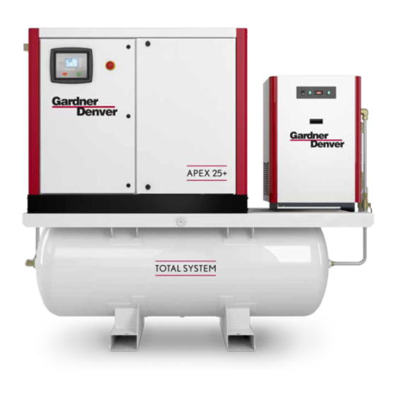
Page 13: Figure 1-4 - Compressor Illustration - Total System
301USC804-A (Ref. Drawing) Page 1 of 1 Figure 1-4 – COMPRESSOR ILLUSTRATION - TOTAL SYSTEM... -
Page 14: Section 2, Installation
SECTION 2 INSTALLATION GENERAL - On receipt of the unit, check for any damage that may have been incurred during transit. Report any damage or missing parts as soon as possible. Do not electric weld on the compressor or base; bearings can be damaged by passing of current. -
Page 15: Figure 2-1 - Typical Compressor Room
For continuous efficiency, the cooler cores must be periodically cleaned with either vacuum or compressed air. If wet cleaning is required, shield motor and spray on a mild soap solution and flush with clean water. NOTICE Coolers are aluminum; do not use any cleaning solution that is not compatible with aluminum. -
Page 16: Figure 2-3 - Cold Weather Installation
ENCLOSURE - The compressor, electric motor, oil cooler and after cooler are mounted inside the enclosure. Service panels are provided for maintenance access. Be sure to allow enough space around the unit for the panels to be removed. Any of the enclosure panels may be removed by opening the latch and lifting it up slightly. - Page 17 When the unit must be installed in an outdoors installation and/or exposed to ambient temperatures below freezing (32 F, 0 C), contact Gardner Denver for recommendations. When using a Total System with a compressed air dryer option, refer to Section 10 for details. Unsheltered (outdoors) installation shall be avoided. Installation next to a heated building may be sufficient to keep the compressor package room above freezing temperature and thus avoid operational complications.
-
Page 18: Figure 2-4 - Electrical Wiring Sizing - Fs Variants
When piping two or more rotary screw units on a common discharge line, each unit shall be isolated by the check valve in the unit discharge line. If a rotary screw and a reciprocating compressor are piped to a common discharge line, an air receiver must be located between the two units. - Page 19 Power Phase-Voltage Max Current Draw - amps 18 / 22 KW package 3-575 41.0 / 41.0 " 3-460 61.0 / 61.0 " 3-230 91.0 / 91.0 RES 120 dryer 1-115 18.3 RES 140 dryer 1-115 18.3 Figure 2-5 – Electrical Wiring Sizing – VS Variants Line Reactor (VS var) –...
-
Page 20: Section 3, Starting & Operating Procedures
For instructions on checking the oil and the proper oil level, refer to “Oil level gauge”, SECTION 5 see page 53 Do not mix different type oils. Standard Unit is shipped filled with Gardner Denver AEON 4000 lubricant which is suitable for the first 4000 hours under normal operating conditions. Other AEON lubricants are available. - Page 21 Failure to properly ground the compressor package could result in controller malfunction. Rotation - Check for correct motor rotation by jogging the motor. See “Maintenance, Motor Jog” menu in Controller Operating and Service Manual. Compressor drive shaft rotation must be: For Direct-Drive compressor, counterclockwise when facing the compressor shaft.
- Page 22 10. Target Pressure - This is the package discharge pressure that the controller would maintain. For fixed speed units, a pressure rise of 3psi above the target value would result in an unload action. For flow modulating units (e.g., variable speed or inlet throttling), a pressure rise above the target would result in flow modulation.
- Page 23 The controller has an automatic start/stop sequence built in. You do NOT need to close the air service valve. Closing the air service valve on start-up or prior to shutdown will cause rapid cycling, and could cause a high pressure shutdown.
- Page 24 Quick Start Guide For your convenience, the following excerpt from the Controller Operating and Service Manual is presented to assist in programming the basic operating parameters. However, we strongly recommend you read the Controller Operating and Service manual before attempting operating the compressor package.
-
Page 25: Section 4, Controls & Instrumentation
CONTROLS & INSTRUMENTATION GENERAL DESCRIPTION The Gardner Denver rotary screw compressor is pre-wired with all controls, motor and starter to match specific voltage and horsepower as ordered. It is necessary only to connect the compressor unit to the correct power supply and to the shop air line. A standard package unit consists of the modular compressor assembly, air/oil cooling and filtration system, control components, electric motor drive, associated starting module, sound attenuation metal enclosure and common support steel base. - Page 26 Power Supply – This single-phase device supplies all 24 VDC needs within the control enclosure from the available AC supply line. Terminal Strip - This device provides an interconnection between the ASG2 controller and the low voltage hardware such as sensors and switches within the enclosure. Main Starter - Hardware details will vary with the type of speed regulation ordered: ·...
-
Page 27: Figure 4-2 - Wiring Diagram - Vs (230 Volt)
306USC546-01 (Ref. Drawing) Page 1 of 4 Figure 4-2 – WIRING DIAGRAM – VS (230 VOLT) - Page 28 306USC546-01 (Ref. Drawing) Page 2 of 4 Figure 4-3 – WIRING DIAGRAM – VS (230 VOLT)
- Page 29 306USC546-01 (Ref. Drawing) Page 3 of 4 Figure 4-3 – WIRING DIAGRAM – VS (230 VOLT)
- Page 30 306USC546-01 (Ref. Drawing) Page 4 of 4 Figure 4-3 – WIRING DIAGRAM – VS (230 VOLT...
- Page 31 307USC546-02 (Ref. Drawing) Page 1 of 4 Figure 4-3– WIRING DIAGRAM – VS (575 VOLT)
- Page 32 307USC546-02 (Ref. Drawing) Page 2 of 4 Figure 4-4 – WIRING DIAGRAM – VS (575 VOLT)
- Page 33 307USC546-02 (Ref. Drawing) Page 3 of 4 Figure 4-4 – WIRING DIAGRAM – VS (575 VOLT)
- Page 34 307USC546-02 (Ref. Drawing) Page 4 of 4 Figure 4-4 – WIRING DIAGRAM – VS (575 VOLT)
- Page 35 311USC546-01 (Ref. Drawing) Page 1 of 4 Figure 4-4 – WIRING DIAGRAM – VS (380-460 VOLT)
- Page 36 311USC546-01 (Ref. Drawing) Page 2 of 4 Figure 4-5 – WIRING DIAGRAM – VS (380-460 VOLT)
- Page 37 311USC546-01 (Ref. Drawing) Page 3 of 4 Figure 4-5 – WIRING DIAGRAM – VS (380-460 VOLT)
- Page 38 311USC546-01 (Ref. Drawing) Page 4 of 4 Figure 4-5 – WIRING DIAGRAM – VS (380-460 VOLT)
-
Page 39: Figure 4- 5 - Wiring Diagram - Fs (208 - 230, 460 Volt)
308USC546-01 (Ref. Drawing) Page 1 of 3 Figure 4- 5 – WIRING DIAGRAM – FS (208 – 230, 460 VOLT) - Page 40 308USC546-01 (Ref. Drawing) Page 2 of 3 Figure 4-6 – WIRING DIAGRAM – FS (208 – 230, 460 VOLT)
- Page 41 308USC546-01 (Ref. Drawing) Page 3 of 3 Figure 4-6 – WIRING DIAGRAM – FS (208 – 230, 460 VOLT)
- Page 42 310USC546-01 (Ref. Drawing) Page 1 of 3 Figure 4- 6 – WIRING DIAGRAM – FS (380-415, 460 VOLT)
- Page 43 310USC546-01 (Ref. Drawing) Page 2 of 3 Figure 4-7 – WIRING DIAGRAM – FS (380-415, 460 VOLT)
- Page 44 310USC546-01 (Ref. Drawing) Page 3 of 3 Figure 4-7 – WIRING DIAGRAM – FS (380-415, 460 VOLT)
- Page 45 309USC546-01 (Ref. Drawing) Page 1 of 3 Figure 4- 7 – WIRING DIAGRAM – FS (575 VOLT)
- Page 46 309USC546-01 (Ref. Drawing) Page 2 of 3 Figure 4-8 – WIRING DIAGRAM– FS (575 VOLT)
- Page 47 309USC546-01 (Ref. Drawing) Page 3 of 3 Figure 4-8 – WIRING DIAGRAM – FS (575 VOLT)
- Page 48 MISCELLANEOUS CONTROL DEVICES - Refer to Figure 4- 8, page 52 for the schematic diagram of the control system. Intake [Air] Filter (1) - Captures solid impurities in the air stream entering compressor inlet. It also attenuates noise emitted by the compressor inlet. Inlet-Valve Assembly (2) - This device controls the intake of atmospheric air entering the compressor during the Load/Unload or the optional Inlet Modulation operational phases: ·...
- Page 49 3/2 Solenoid Valve (Y) - This valve controls the position of the inlet valve in response to signals from the AirSmart Controller. It also provides a small amount of scavenge air to carry off compressor shaft seal oil challenge. See inlet valve assembly (2) for more information. Pressure Sensor - Sump Dry Side (B1) - This device is connected after the minimum pressure valve.
- Page 50 Shuttle valve (30.1) – This device taps compressed air for the modulation system from within the package or the customer grid, avoiding supply pressure lapses during start-up. Pressure regulator and Gauge (30.2) – These devises regulate and indicate the compressed air signal that is used by the modulation system.
-
Page 51: Figure 4- 8 - Piping And Instrumentation Illustration
301USC797-C (Ref. Drawing) Figure 4- 8 – PIPING AND INSTRUMENTATION ILLUSTRATIONJ... -
Page 52: Figure 5-1 - Oil Level Sight Glass
AEON lubricants are available through your authorized Gardner Denver compressor distributor. OIL SPECIFICATIONS - The standard factory fill compressor lubricant is Gardner Denver AEON 4000, a superior semi-synthetic blend of petroleum stock and various protective additives, suitable for year-round operation. - Page 53 Before draining, adding, or changing the lubricant oil in the compressor, be aware of the following hazards associated with these tasks: Air/oil under pressure will cause severe personal injury or death. Shut down compressor, relieve system of all pressure, disconnect, tag and lockout power supply to the starter before removing valves, caps, plugs, fittings, bolts and filters.
- Page 54 All materials used in Gardner Denver compressor units are compatible with AEON 9000SP Lubricant. Use caution when selecting downstream components such as air line lubricating bowls, gaskets and valve trim. AEON 9000SP Synthetic Lubricant is not compatible with low nitrile Buna N or acrylic paints.
- Page 55 ADDITION OF OIL BETWEEN CHANGES must be made when the oil level is below the minimum level of the sight glass as read while the unit is completely off and blown down, and the foam has settled out. Be sure the unit is completely off and that no air pressure is in the oil reservoir. Disconnect, tag and lockout the power supply to the starter.
-
Page 56: Figure 5-2 - Dew Point Chart °F
Pressure Dew Point Trend (100% r.h.) 100psig 125psig 150psig 175psig Am bient Tem p - oF Figure 5-2 – Dew Point Chart °F Pressure Dew Point Trend (100% r.h.) 6.9bar 8.6bar 10.3bar 12.1bar 10.0 15.0 20.0 25.0 30.0 35.0 40.0 45.0 50.0 Ambient Temp - oC... -
Page 57: Figure 5-4 - Oil Change Interval
Operating conditions and the appearance of the drained oil must be surveyed and the oil change intervals planned accordingly by the user. Gardner Denver offers a free oil analysis program with the AEON lubricants, and we recommend a sample be sent in at 100 hours on a new unit. - Page 58 Optional Element. If the compressor is used in a predominantly cold (<32ºF, 0ºC) and/or humid environment, proper oil viscosity and avoidance of water vapor condensation in the oil system may be achieved by using a higher setting (158ºF, 70ºC) thermostatic element. Consult Gardner Denver for details.
- Page 59 OIL SUMP (RESERVOIR) - This device provides the inertial separation of air and oil streams discharged by the compressor - the bulk (98%) of the air/oil separation is done at this step. It also serves as a holding and degassing volume for the major portion of the oil charge. It provides limited air storage for control and gauge actuation.
- Page 60 7. Run the unit and check for leaks. 336LSE810-B (Ref. Drawing) Figure 5-4 Air/Oil Separation Housing Illustration 13-25-608 Page 59...
-
Page 61: Section 6, Heat Exchangers (Oil/Air)
HEAT EXCHANGER MAINTENANCE - All the required hardware, mechanical and electrical connections have been made at the Gardner Denver factory, thus the only regular maintenance required is to keep the exterior core fins free from dirt and other airborne debris per the following procedure:... - Page 62 Compressor, air/oil sump and all piping and tubing may be at high temperature during and after operation. Do not attempt inspection or cleaning of air-cooled heat exchangers until cooling fan has stopped rotating. Disconnect lockout and tag out package from power supply.
-
Page 63: Figure 6-2 - Cooler Access
The ventilation system for the air-cooled package relies on positive back pressure to cool the heat exchanger. Make sure that the access panel next to the heat exchanger is closed during operation, or the compressor discharge temperature will reach shutdown levels quickly. FIGURE 6- 2 –... -
Page 64: Section 7, Air Filters
In turn, the longevity of the filter element depends on the cleanliness of the local environment. NOTICE Use only genuine Gardner Denver air filter elements on Gardner Denver compressor units. Genuine parts are available through your authorized Gardner Denver distributor. -
Page 65: Figure 7-1 - Compressor Air Filter, Package Pre-Filter And Vfd Filter Locations
PACKAGE PRE-FILTER MAINTENANCE Cleanse the pre-filter media with vacuum cleaner to remove debris trapped in its fibers. The media may be removed from the intake air grill frame if washing is needed to remove dirt. Replace the pre-filter media in the reverse order. VFD FILTER MAINTENANCE Remove the intake air grill panel from the package by first removing the top-located screws and washers. -
Page 66: Figure 8- 1 - Coupling Components
SECTION 8 DRIVE SHAFT COUPLING SHAFT COUPLING – The main motor drives the compressor by means of a curved jaw-type coupling. Each coupling hub is fixed to the shaft with a set screw and key combination. The motor power is delivered to the compressor via a single, vibrations damping element –... -
Page 67: Figure 8- 2 - Coupling Element Spacing
4. If coupling gap did not exceed 2-3mm beyond its nominal limit of 24/25.8mm, loosen M8 set screw on motor coupling hub and move to close gap to nominal limit. If coupling gap is still within its nominal limits of 24/25.8 mm, verify that each M8 set screw fixing the hub to the shaft is tight. If either hub set screw is loose, apply a locking compound to its threads and tighten to 10 N-m torque. -
Page 68: Figure 8- 3- Compressor-Motor Assembly Details
8. Re-assembly the compressor and associated components in reverse order. Remember to set the proper spacing between the coupling jaws (24/25.8mm) and tighten the M8 set screws to the proper torque (10 N-m). FIGURE 8- 3- COMPRESSOR-MOTOR ASSEMBLY DETAILS Installation and Removal of Interference Fitted Coupling Hubs. The coupling hubs are designed to mount on the compressor and motor shafts with a transitional interference fit [H7 (bore) / k6 (shaft)] that results in a light interference 50% of the time. -
Page 69: Section 9, Servicing Of Miscellaneous Devices
SECTION 9 SERVICING OF MISCELLANEOUS DEVICES This section will cover basic maintenance of various control devices used with the compressor module. Refer to Fig 9-1, Page 70, for pictorials of referenced hardware. INLET CONTROL VALVE ASSEMBLY Inlet-Valve Assembly (2) - This device is located within and below the intake flange of the compressor - see Fig. -
Page 70: Figure 9-2 - Inlet Valve Body Hex
Inlet Valve (Body) Inspection - The valve does not require maintenance or lubrication. If air/oil leaks develop across the valve disc during pressurized conditions (e.g., machine stopped), valve seals should be inspected for wear and tear signs: 1. Be sure the unit is completely off and oil sump is depressurized. 2. -
Page 71: Figure 9-3 - Pressure Relief Valve
PRESSURE RELIEF VALVE Pressure Relief Valve - This device protects the pressure-containing components of the compressor package against pressures exceeding 200 psig. It is installed on the wet-side of the oil sump. FIGURE 9- 3 - Pressure relief valve Before inspecting the pressure relief valve, release air pressure, lockout and tagout the power supply to the compressor package. -
Page 72: Figure 9-4 - Minimum Pressure Valve And Seat
MINIMUM PRESSURE VALVE Minimum Pressure Valve Inspection – This device has no user-serviceable or repairable components. If it fails to maintain adequate minimum pressure (55-65psig) or fails to check the backflow of system compressed air after compressor stoppage, replace it as follows: FIGURE 9- 4 - Minimum Pressure Valve and Seat Air/oil pressure will cause severe personal injury or death. -
Page 73: Figure 9-5 - Thermal Mixing Valve
The stamped setting on the valve seat is not correct. The Fixed Speed compressor package should be fitted with the 55ºC TMV, unless by consultation with Gardner Denver, it has been approved to use the 70ºC element instead. - Page 74 Parts List Manual listed on Page 5. Be aware that replacement of the shaft seal assembly involves removing the compressor from the package, an operation that may be best handled by an experienced Gardner Denver technician. Shaft Seal Replacement (applies to both direct drive and geared drive compressors): Have the proper shaft seal replacement kit available.
- Page 75 308USC810-C (Ref. Drawing) FIGURE9- 1 – Compressor (Direct Drive variant) Hardware Illustration...
- Page 76 SECTION 10 TANK MOUNTED COMPRESSOR - TOTAL SYSTEM DESCRIPTION - The basic compressor can be furnished mounted on an optional compressed air receiver (240 gallon size) and paired to an optional RNC [refrigerated non-cycling] compressed air dryer, as shown on Fig 10-1. ·...
- Page 77 · Installation - Package must installed in a location with an ambient temperature range of 40ºF to 110ºF (3ºC to 43ºC). Consult Gardner Denver for operation outside this range. · Discharge service pipe - The discharge service line connection is provided at the outlet of the bypass valve assembly.
- Page 78 SECTION 11 MOTOR LUBRICATION Rotating machinery can cause injury or death. Open main disconnect, lockout and tagout power supply to compressor package before working on the electric motor. Motor Lubrication – Long time satisfactory operation of an electric motor depends in large measure on the proper lubrication of the bearings.
-
Page 79: Section 10, Maintenance Schedule
SECTION 12 MAINTENANCE SCHEDULE SERVICE CHECK LIST – Air Filter and Pre-Filter - Operating conditions determine frequency of service. See “Air Filter,” SECTION 7, page 65. Motor Lubrication - Refer to Section 2, page 13 Every 8 Hours Operation Check the reservoir oil level - add oil if required. See Section 11, page 79. Observe if the unit loads and unloads properly. -
Page 80: Section 10, Maintenance Schedule
MAINTENANCE SCHEDULE (See Detail Notes above) Maintenance Action As Indicated Every Every Every Every Every Every by AirSmart 1000 4000 Year Controller Hours Hours Hours Hours Hours · Check/Change Air Filter ..........· Check/Change Package Inlet Filters ......· · Change Oil Separator .......... -
Page 81: Section 11, Troubleshooting
SECTION 13 TROUBLESHOOTING SYMPTOM POSSIBLE CAUSE REMEDY Compressor fails to start No electrical power. Check main disconnect, fuses and supply line. [FS] Motor starter Reset and investigate overload relay tripped. cause of overload. Pressure in reservoir. Inspect unload valve. Wrong lead connections Change leads. - Page 82 SYMPTOM POSSIBLE CAUSE REMEDY Compressor starts too [FS] Wye Delta switch Contact your Gardner slowly time set too long. Denver distributor. Minimum Pressure Valve Inspect and/or replace. is faulty. Supply voltage is too low. Check the supply voltage. Acceleration time on vfd Contact GD for help.
- Page 83 Inspect and cleanse. Ruptured oil separator Replace element. element. Loose assembly. Tighten all fittings and gaskets. Foaming caused by use of Use Gardner Denver incorrect oil. AEON 4000 or 9000SP lubricating coolant. Inoperative minimum Inspect and/or replace. pressure valve. Operation at elevated Reduce temperature.
- Page 84 Look for poor connections or undersized wiring. NOTICE Gardner Denver factory remanufactured replacement compressor air end units are available from your authorized distributor, on an exchange basis, for all rotary screw compressor units.
- Page 85 HR Series STANDARD WARRANTY Gardner Denver (the “Company”) warrants to each original retail purchaser (“Purchaser”) of its new products from the Company or its authorized distributor that such products are, at the time of delivery to the Purchaser, free of defects in material and workmanship.
- Page 86 For additional information, contact your local representative or visit: www.contactgd.com/compressors ©2016 Gardner Denver, Inc. Printed in U.S.A.
Need help?
Do you have a question about the APEX25-30A and is the answer not in the manual?
Questions and answers