Sign In
Upload
Manuals
Brands
Gardner Denver Manuals
Air Compressor
APEX15-18A
Gardner Denver APEX15-18A Manuals
Manuals and User Guides for Gardner Denver APEX15-18A. We have
1
Gardner Denver APEX15-18A manual available for free PDF download: Operating And Service Manual
Gardner Denver APEX15-18A Operating And Service Manual (70 pages)
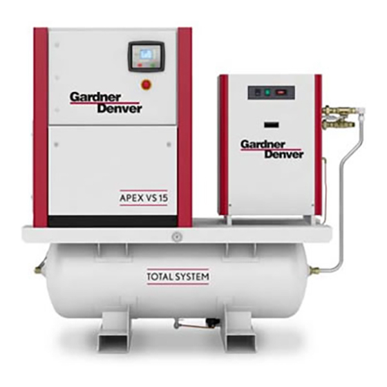
SINGLE STAGE BASE-MOUNTED and TANK MOUNTED COMPRESSORS AirSmart G2 Controller
Brand:
Gardner Denver
| Category:
Air Compressor
| Size: 4.24 MB
Table of Contents
Support Services
3
Instructions for Ordering Repair Parts
3
Warning - Prohibition - Mandatory Label Information
4
Safety Precautions
6
Table of Contents
7
Index
8
Figure 1-1 - Compressor Cycle
10
Section 1, General Information
10
Figure 1-2 - Compressor Illustration - External Details
11
Figure 1-3 - Compressor Illustration - Internal Details
12
Section 2, Installation
14
Figure 2-1 - Typical Compressor Room
15
Figure 2-2 - Air Flow Chart
15
Figure 2-3 - Cold Weather Installation
16
Section 3, Starting & Operating Procedures
20
Figure 4-1 - Controller Layout and Main Screen
25
Section 4, Controls & Instrumentation
25
Figure 4-4 - Wiring Diagram - Wye-Delta (200-230/460 Volt)
27
Figure 4-4 - Wiring Diagram - Wye-Delta (200-230/460 Volt)
29
Figure 4-4 - Wiring Diagram - Wye-Delta (200-230/460 Volt)
30
Figure 4-5 - Wiring Diagram - Wye-Delta (575 Volt)
31
Figure 4-5 - Wiring Diagram - Wye-Delta (575 Volt)
32
Figure 4-5 - Wiring Diagram - Wye-Delta (575 Volt)
33
Figure 4-5 - Wiring Diagram - Wye-Delta (575 Volt)
34
Figure 4 6 - Piping and Instrumentation Illustration
37
Section 5, Lubrication. Oil Cooler, Oil Filter & Separator
38
Figure 5-1 - Oil Level Sight Glass
38
Figure 5-2 - Dew Point Chart °F
42
Figure 5-3 - Dew Point Chart °C
42
Figure 5-4 - Oil Change Interval
43
Section 6, Heat Exchangers (Oil/Air)
46
Figure 6-1 - Air Flow Chart
46
Figure 6-2 - Cooler Access
48
Section 7, Air Filters
49
Figure 7-1 - Compressor Air Filter
50
Figure 7-2 - Pre-Filter Cover, Pre-Filter and Fan Grill
50
Section 8, Belt Drive System
52
Figure 8-1 - Motor Jacking Assembly
52
Figure 8-2 - V-Belt Drive Components
52
Figure 8-3 - Measuring Angular Misalignment
53
Section 9, Servicing of Miscellaneous Devices
55
Figure 9-1 - Inlet Valve Assembly
55
Figure 9-2 - Inlet Valve Body Hex
56
Figure 9-3 - Pressure Relief Valve
57
Figure 9-4 - Minimum Pressure Valve and Seat
58
Figure 9-5 - Thermal Mixing Valve
59
Figure 9-6 - Compressor Module Hardware
60
Section 10, Tank Mounted Compressor - Total System
61
Figure 10-1- Total System Arrangement
61
Section 11, Maintenance Schedule
63
Section 12, Troubleshooting
65
Advertisement
Advertisement
Related Products
Gardner Denver APEX25-30A
Gardner Denver APEXVS18-22A
Gardner Denver AirSmart Controller APEX5-15A
Gardner Denver APEXVS7-11A
Gardner Denver APEX25-30B
Gardner Denver APEXVS18-22B
Gardner Denver AUTOSENTRY EAQ99Q
Gardner Denver AUTOSENTRY EBQ99M
Gardner Denver AUTOSENTRY EAU99Q
Gardner Denver AUTOSENTRY EBU99C
Gardner Denver Categories
Air Compressor
Water Pump
Dehumidifier
Controller
Blower
More Gardner Denver Manuals
Login
Sign In
OR
Sign in with Facebook
Sign in with Google
Upload manual
Upload from disk
Upload from URL