Advertisement

S
ervice
M anua l
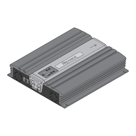
BRIDGEABLE POWER AMPLIFIER
GM-X822
GM-X722
CONTENTS
1. SAFETY INFORMATION ............................................2
2. EXPLODED VIEWS AND PARTS LIST .......................3
3. SCHEMATIC DIAGRAM .............................................8
4. PCB CONNECTION DIAGRAM ................................12
5. ELECTRICAL PARTS LIST ........................................15
PIONEER ELECTRONIC CORPORATION
PIONEER ELECTRONICS SERVICE INC.
PIONEER ELECTRONIC [EUROPE] N.V.
PIONEER ELECTRONICS ASIACENTRE, PTE.LTD. 501 Orchard Road, #10-00, Wheelock Place, Singapore 238880
C PIONEER ELECTRONIC CORPORATION 1998
4-1, Meguro 1-Chome, Meguro-ku, Tokyo 153-8654, Japan
P.O.Box 1760, Long Beach, CA 90801-1760 U.S.A.
Haven 1087 Keetberglaan 1, 9120 Melsele, Belgium
X1R/UC,ES,EW
6. ADJUSTMENT..........................................................19
7. GENERAL INFORMATION .......................................20
7.1 IC .........................................................................20
7.2 DISASSEMBLY ...................................................21
7.3 BLOCK DIAGRAM ..............................................22
8. OPERATIONS AND SPECIFICATIONS.....................23
K-ZEB. FEB. 1998 Printed in Japan
ORDER NO.
CRT2187
X1R/UC

Advertisement

Table of Contents
loading

Summary of Contents for Pioneer GM-X822 X1R/UC

  • Page 1: Table Of Contents

    P.O.Box 1760, Long Beach, CA 90801-1760 U.S.A. PIONEER ELECTRONIC [EUROPE] N.V. Haven 1087 Keetberglaan 1, 9120 Melsele, Belgium PIONEER ELECTRONICS ASIACENTRE, PTE.LTD. 501 Orchard Road, #10-00, Wheelock Place, Singapore 238880 C PIONEER ELECTRONIC CORPORATION 1998 K-ZEB. FEB. 1998 Printed in Japan...
  • Page 2: Safety Information

    GM-X822,X722 1. SAFETY INFORMATION UC model CAUTION This service manual is intended for qualified service technicians; it is not meant for the casual do-it-yourselfer. Qualified technicians have the necessary test equipment and tools, and have been trained to properly and safely repair complex products such as those covered by this manual.
  • Page 3: Exploded Views And Parts List

    GM-X822,X722 2. EXPLODED VIEWS AND PARTS LIST 2.1 PACKING Fig. 1...
  • Page 4 GM-X822,X722 NOTE: Parts marked by “*”are generally unavailable because they are not in our Master Spare Parts List. Screws adjacent to ∇ mark on the product are used for disassembly. - PACKING SECTION PARTS LIST Part No. GM-X822 GM-X722 Mark No. Description X1R/UC X1R/UC...
  • Page 5 GM-X822,X722 2.2 EXTERIOR Fig. 2...
  • Page 6 GM-X822,X722 (1) EXTERIOR SECTION PARTS LIST Mark No. Description Part No. Mark No. Description Part No. 1 Screw BMZ30P250FZK 36 Clamper HNV0015 2 Screw(M3x12) CBA1323 37 Spacer HNV3975 3 Screw(M3x14) CBA1382 38 Screw BMZ30P250FZK 4 Sheet CNM5854 39 Fan Motor CXM1102 5 Screw HBA0006...
  • Page 7 GM-X822,X722 (2) CONTRAST TABLE GM-X822/X1R/UC, GM-X722/X1R/UC, GM-X722/X1R/ES and GM-X722/X1R/EW are constructed the same except for the following: Part No. GM-X822 GM-X722 Mark No. Symbol and Description X1R/UC X1R/UC X1R/ES X1R/EW Amp Unit HWH0075 HWH0076 HWH0074 HWH0073 Spacer HNM0053(x2) HNM0053(x2) HNM0053(x1) HNM0053(x2) Film CNM5856...
  • Page 8: Schematic Diagram

    GM-X822,X722 3. SCHEMATIC DIAGRAM 3.1 AMP UNIT Note: When ordering service parts, be sure to refer to "EXPLODED VIEWS AND PARTS LIST" or "ELECTRICAL PARTS LIST". AMP PCB -10dBs -7.6dBs AUDIO PCB -10.2dBs BASS 15.5V -15.5V AMP UNIT Consists of AMP PCB AUDIO PCB BASS PCB...
  • Page 9 GM-X822,X722 -14.3dBs 21.3dBs 0.1V 3.2V 3.5V 0.3V 3.8V 0.2V 1.9V 14.4V 5.0V 14.3V 5.0V 0.2V 10.7V 2.6V 5.0V 0.2V 14.4V 2.4V 2.4V 6.3V Fig. 3...
  • Page 10 GM-X822,X722 3.2 AUDIO PCB AND BASS PCB Fig. 4...
  • Page 11 GM-X822,X722...
  • Page 12: Pcb Connection Diagram

    GM-X822,X722 4. PCB CONNECTION DIAGRAM AMP PCB 4.1 AMP UNIT FAN MO NOTE FOR PCB DIAGRAMS 1. The parts mounted on this PCB include all necessary parts for several destination. For further information for respective destinations, be sure to check with the schematic dia- gram.
  • Page 13 GM-X822,X722 AN MOTOR CN553 Fig. 5...
  • Page 14 GM-X822,X722 AUDIO PCB CN552 CN501 Fig. 6 BASS PCB CN551 CN503 Fig. 7...
  • Page 15: Electrical Parts List

    GM-X822,X722 5. ELECTRICAL PARTS LIST NOTE: - Parts whose parts numbers are omitted are subject to being not supplied. - The part numbers shown below indicate chip components. Chip Resistor RS1/_S___J,RS1/__S___J Chip Capacitor (except for CQS..) CKS.., CCS.., CSZS..=====Circuit Symbol and No.===Part Name Part No.
  • Page 16 GM-X822,X722 =====Circuit Symbol and No.===Part Name Part No. =====Circuit Symbol and No.===Part Name Part No. ------ --------------------------------------------- ------------------------- ------ --------------------------------------------- ------------------------- Ferri-Inductor CTF1007 0.22Ω CCN1071 Choke Coil 50mH CTH1144 0.22Ω CCN1071 Choke Coil 200mH CTH1211 RD1/2PM100J Choke Coil 200mH CTH1211 RD1/4PU103J Transformer CTT1081...
  • Page 17 GM-X822,X722 =====Circuit Symbol and No.===Part Name Part No. =====Circuit Symbol and No.===Part Name Part No. ------ --------------------------------------------- ------------------------- ------ --------------------------------------------- ------------------------- RD1/4PU472J RD1/4PU681J RD1/4PU101J RD1/4PU272J CAPACITORS RD1/4PU272J RD1/4PU272J CEAS100M16 CQPA221G2A RD1/4PU223J CQPA102G2A RD1/4PU223J CFTLA104J50 RD1/4PU223J CEAS101M16 RD1/4PU223J RD1/4PU223J CMA150J2H CFTLA104J50 RD1/4PU821J CMA330J2H RD1/4PU821J...
  • Page 18 GM-X822,X722 =====Circuit Symbol and No.===Part Name Part No. =====Circuit Symbol and No.===Part Name Part No. ------ --------------------------------------------- ------------------------- ------ --------------------------------------------- ------------------------- CCPUSL470J50 4700µF/16V CCH1310 CCPUSL470J50 CEAS332M35 CFTLA104J50 CEAS332M35 CFTLA224J50 CEAS332M35 CFTLA104J50 CEAS332M35 CEAS100M16 CEAS470M16 CEAS221M10 CEAS470M16 CQMAQ102J50 CEAS101M16 CFTLA105J50 CEAS101M16 CEAS101M16 CEAS331M50 CFTLA564J50...
  • Page 19: Adjustment

    GM-X822,X722 6. ADJUSTMENT No. Item Conditions Adjustment point Specifications 1 Idling current Input ; adjust 30 seconds after 1kΩ terminate VR101(Lch) mV Meter(1) : 12mV±3mV (adjustment) power is switched on, and within 20 seconds. VR201(Rch) 2 DC-DC converter Input ; adjust 30 seconds after 1kΩ terminate VR951 mV Meter(2) : 30V±3V voltage...
  • Page 20: General Information

    GM-X822,X722 7. GENERAL INFORMATION 7.1 IC PA2027A Transient voltage detector Stby Bandgap DET1 Circuit motion:on DET2 Cont_V 50µA DET_R Filter 4.7kΩ Bandgap:on Switch:on Vs_out 0.13V Mute_out 5.6V Oneshot (1µsec)
  • Page 21: Disassembly

    GM-X822,X722 7.2 DISASSEMBLY - Removing the Case and Panel Units 1. Remove eight screws A and then remove Case. 2. Remove two screws B and seven screws E and then remove Panel Units. Fig. 9 - Removing the Amp Unit 1.
  • Page 22: Block Diagram

    GM-X822,X722 7.3 BLOCK DIAGRAM Fig. 11...
  • Page 23: Operations And Specifications

    GM-X822,X722 8. OPERATIONS AND SPECIFICATIONS - CONNECTION DIAGRAM (1) GM-X822/X1R/UC Connection Diagram Fuse (30 A) Special red battery wire [RD-223] (sold separately). After making all other connections at the amplifier, Grommet connect the battery wire terminal of the amplifier to the positive (+) terminal of the battery.
  • Page 24 GM-X822,X722...
  • Page 25 GM-X822,X722...
  • Page 26 GM-X822,X722...
  • Page 27 GM-X822,X722 SPECIFICATIONS Power source ......................14.4 V DC (10.8 — 15.1 V allowable) Grounding system ............................Negative type Current consumption ......................22.5 A (at continuous power, 4 Ω) Average current drawn* ......................6.5 A (4 Ω for two channels) 11.3 A (4 Ω for one channel) Fuse ....................................

This manual is also suitable for:

Gm-x722 x1r/ucGm-x722 x1r/esGm-x722 x1r/ew

Table of Contents