Febco 825YD Series Installation Instructions
Hide thumbs
Also See for 825YD Series:
- Installation operation & maintenance (34 pages) ,
- Installation operation & maintenance (4 pages)
Advertisement
Quick Links
I N S T A L L A T I O N I N S T R U C T I O N S
Installation Instructions
1. Consult local codes for specific installation requirements and restrictions
applicable to your area. It is recommended that system supply pressure
be at least 20psi (133kPa).
2. These instructions apply to series 825YD, and 826YD size 2
250mm) only. The valves may be installed only in the horizontal orienta-
tion as shown.
3. The valve assembly must be installed where it is accessible for periodic
testing and maintenance. Clearances shown in the installation views
apply to exterior, interior and pit/vault installations and are only recom-
mendations. These minimums do not apply to removable protective
enclosures. Refer to local codes for actual requirements in your area.
4. PRIOR TO INSTALLING THE VALVE INTO THE LINE, FLUSH THE SUP-
PLY LINE OF ALL FOREIGN MATERIAL. Failure to flush the supply line
may cause the check valves to become fouled and require disassembly
and cleaning.
5. DO NOT LIFT THE ASSEMBLY BY CONNECTING TO THE GATE VALVE
HANDWHEELS OR STEMS.
6. After installation SLOWLY fill the assembly with water and bleed air from
the body using the #2, # 3 and # 4 test cocks. Test the valve assembly to
ensure correct operation.
NOTE: All assemblies are tested at the factory for proper operation and
leakage. If the valve does not pass the field test, it is most likely due to a
fouled check valve. This is not covered by the factory warranty. The valve
cover(s) must be removed and the check seats inspected and cleaned.
Any damage or improper operation caused by pipeline debris or improp-
er installation/start-up is not included in the factory warranty.
In case of a possible warranty claim, contact your local supplier or
FEBCO Representative. DO NOT REMOVE THE VALVE ASSEMBLY
FROM THE PIPELINE.
7. The assembly must be protected from freezing and excessive pressure
increases. Pressure increases can be caused by thermal expansion or
water hammer. These excessive pressure situations must be eliminated
to protect the valve and system from possible damage.
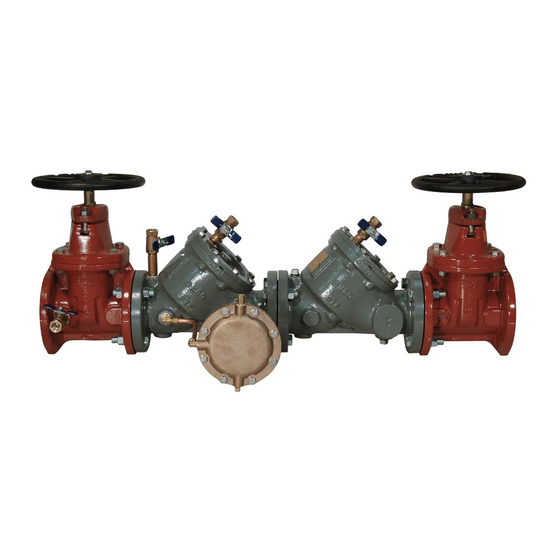
Series 825YD, 826YD
Reduced Pressure Zone Assemblies
Reduced Pressure Detector Assemblies
Typical Installation
1
⁄
" to 10" (65-
2
1
Sizes: 2
⁄
" – 10" (65 – 250mm)
2
826YD
Figure 1
12" (300mm) Minimum
Refer to Local Codes
RWWP
FRT
175
4
FLOW
HORIZONTAL INSTALLATION OF THE RP SERIES 825YD
(Side View)
(Shown With Strainer)
Figure 2
6" (150mm) Minimum
Refer to Local Codes
HORIZONTAL INSTALLATION OF THE RP SERIES 825YD
(Top View)
(Shown With Strainer)
IS-F-825YD-826YD
12" (300mm)
Minimum
18" (450mm) Min
Advertisement

Related Manuals for Febco 825YD Series


Summary of Contents for Febco 825YD Series
- Page 1 In case of a possible warranty claim, contact your local supplier or HORIZONTAL INSTALLATION OF THE RP SERIES 825YD FEBCO Representative. DO NOT REMOVE THE VALVE ASSEMBLY (Top View) FROM THE PIPELINE.
- Page 2 Limited Warranty: FEBCO warrants each product to be free from defects in material and workmanship under normal usage for a period of one year from the date of original shipment. In the event of such defects within the warranty period, the Company will, at its option, replace or recondition the product without charge. This shall constitute the sole and exclusive remedy for breach of warranty, and...